A centrifuge HMI needs to keep operating condition, alarms, and service actions clear in a demanding industrial setting.
Industrial centrifuges are used in separation, chemical processing, food production, wastewater treatment, pharmaceuticals, and materials handling. Their control panels must translate a moving mechanical process into information an operator can act on: speed, run state, feed condition, vibration warning, interlocks, alarms, cleaning cycle, and service status. The display is not a decorative front-panel part. It is a working interface between the machine, controls team, and person responsible for safe output.
For OEMs, selecting a TFT LCD display for an industrial centrifuge means balancing readability, mechanical fit, touch behavior, electrical compatibility, and long-term availability. The right module helps operators make decisions quickly without creating an unnecessary integration risk.
Start With the Operator Workflow
The best display specification begins with the actual operating sequence, not a diagonal-size preference. Map what users need to see during start-up, normal separation, recipe change, alarm response, cleaning, shutdown, and maintenance. A local controller may require only clear state, setpoint, warning, and stop information. A more complex skid may need trend views, process relationships, batch records, permissions, and diagnostic pages.
Identify the real viewing position. A panel mounted on the machine may be viewed while standing beside a guard or from an angle during service. If the product is operated from several positions, IPS TFT LCD modules can provide more stable contrast and color than a narrow-angle option. Confirm the required optical performance with the installed panel orientation, not just a datasheet number.
Make Alarms and Process State Easy to Read
Centrifuge operators should not need to decode a crowded screen when a condition changes. Separate normal operation, attention-required states, and critical alarms with a clear visual hierarchy. Reserve the strongest contrast and color for conditions that need an immediate response. Keep vital values large enough for the intended distance and avoid using color alone to communicate a fault.
Brightness and front-surface treatment matter as much as the LCD cell. Stainless equipment rooms can have strong overhead lighting, washdown reflections, and shadowed service areas. Evaluate the display with the target cover lens, bezel, and mounting angle. A brighter module is helpful only when it also controls reflections and preserves readable contrast.
For equipment families, review standard TFT LCD modules against required resolution, brightness, interface, and lifecycle. This gives the HMI team a stable starting point before custom mechanics are finalized.
Design Touch and Physical Controls Together
Touch is useful for recipes, navigation, acknowledgements, and service functions, but it should not replace every physical control. Emergency-stop and other safety functions need the required hardware design and safety architecture. The touch interface should support gloved use when necessary, prevent accidental activation, and make the current state obvious before a change is applied.
Projected capacitive touch can deliver a clean sealed front surface, while other approaches may suit gloves, moisture, or specific operating environments. For an integrated review of display and touch options, see capacitive touch TFT LCD assemblies. Check cover glass thickness, printed border, sensor tuning, adhesive, and ground strategy with the intended enclosure. These details affect both usability and reliability.
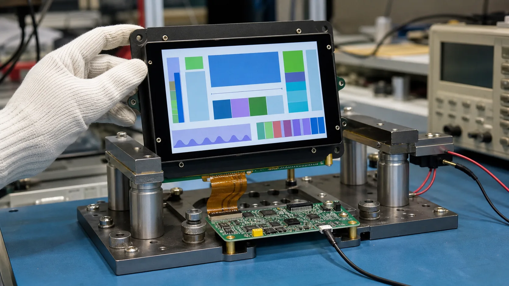 Display, touch, FPC, bezel, controller, and vibration resistance should be checked as one HMI assembly.
Engineer for Vibration, Noise, and Service Access
Rotating equipment can transmit vibration through the skid, cabinet, and display mounting structure. The LCD, touch panel, controller, FPC, connector, and bezel must be treated as one assembly. Avoid unsupported board mass, sharp FPC bends, and mounting points that concentrate stress on the panel. Verify screw torque, gasket compression, connector retention, and cable clearance in a representative unit.
Electrical noise is another practical concern. Motor drives, switching supplies, contactors, and long cable runs can affect display signals and touch performance. Follow the controller and panel recommendations for power sequencing, grounding, shielding, cable routing, and interface impedance. Prototype testing should use the actual drive and wiring arrangement where possible; a quiet bench setup cannot reveal every installation issue.
Temperature, moisture, and cleaning requirements should also be defined early. In outdoor, cold-room, or hot process areas, wide-temperature TFT LCD modules may be relevant. The selected module, cover lens, seals, and adhesives must all support the product environment.
Select Resolution and Interface Around the Control Platform
Resolution should serve the HMI content. A larger panel with insufficient resolution can make trends and small process values hard to read, while an unnecessarily dense panel may increase controller memory and graphic load. Prepare sample screens at the target pixel size and review them on real hardware. Check fonts, warning icons, bar graphs, and live process values rather than relying on a generic demo image.
The display interface must match the mainboard, cable length, controller capability, and boot sequence. Document voltage rails, backlight control, signal routing, FPC direction, connector location, and mechanical tolerances. Early cooperation between the electronics, mechanical, and software teams prevents an apparently suitable module from causing late changes to the enclosure or PCB.
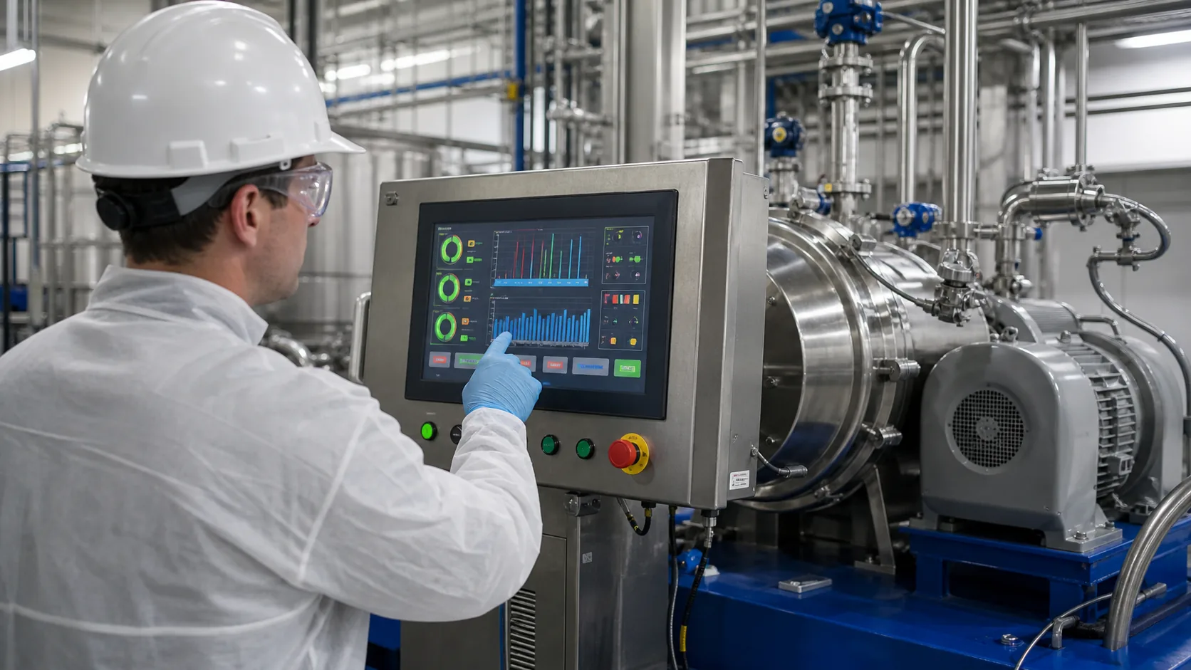 The final HMI should be reviewed with representative start-up, monitoring, alarm, cleaning, and service workflows.
Validate With the Machine, Not Only a Sample Panel
Run validation with the intended centrifuge process and actual HMI software. Test normal operating views, abnormal vibration, lid or interlock conditions, power cycling, emergency procedures, cleaning, glove operation, and service access. Check whether critical status remains readable from the positions operators genuinely use.
The supply plan deserves equal attention. Ask about module lifecycle, change notification, controller availability, optical alternatives, and qualified replacement paths. A control panel is often expected to remain serviceable for years, so stable supply and controlled changes matter as much as the first prototype.
Practical RFQ Checklist
An effective RFQ includes application, viewing distance, display size, active area, resolution, brightness, viewing-angle requirement, touch type, cover lens, interface, operating temperature, vibration exposure, cleaning method, annual volume, and lifecycle target. Share enclosure drawings, screen layouts, and electrical constraints. This lets a supplier recommend appropriate industrial display modules rather than only matching a screen size.
Sunshine Display supports TFT LCD modules for OEM industrial equipment and can help review display, touch, and integration requirements. Contact Sunshine Display to discuss an industrial centrifuge HMI project.
FAQ
What display size is common for a centrifuge control panel?
The right size follows viewing distance, number of process values, alarm hierarchy, and enclosure space. A compact panel can suit a simple local controller, while a larger HMI supports trends, recipes, and maintenance information.
Should a centrifuge HMI use IPS TFT technology?
IPS is useful when the operator views the panel from changing positions or when stable color and contrast are important. The final choice should also account for brightness, temperature, lifecycle, and budget.
How should a TFT LCD be validated for centrifuge equipment?
Test it in the final assembly for vibration, electrical noise, viewing angle, touch operation, cleaning, temperature, connector retention, alarm visibility, and representative operator workflows.