CNC HMI displays must remain usable around coolant, chips, vibration, electrical noise, and fast production workflows.
CNC machining centers depend on an interface that stays clear while the machine is cutting parts. Operators need to confirm program state, tool position, feed and spindle information, alarms, offsets, maintenance prompts, and production status quickly. The display module is one component of a larger CNC control system, but a poor display choice can turn a capable machine into a frustrating and less efficient workstation.
For OEMs, choosing a TFT LCD display for a CNC machine control panel requires more than matching the opening in the enclosure. The module must support the HMI content while fitting an environment with coolant, chips, vibration, glove use, motor noise, cleaning, and a long product lifecycle.
Map the CNC Workflow Before Choosing a Panel
Begin with the screens operators use during setup, cycle start, normal machining, tool changes, alarm recovery, and service. A compact controller may show status, coordinates, and a small set of controls. A larger HMI may need toolpath graphics, fixture views, diagnostic pages, program information, and production data at the same time. Choose active area and resolution around that workflow, not a diagonal-size preference alone.
Viewing position also matters. The control panel may be mounted on a swing arm, built into a door, or viewed from the side while an operator loads a part. When stable readability from different angles is needed, IPS TFT LCD modules are often worth evaluating. Confirm performance with the real panel angle and the final front glass rather than only a straight-on bench view.
Keep Toolpaths, Alarms, and Values Legible
CNC interfaces can become dense quickly. Toolpath lines, coordinate readouts, warning colors, fine icons, and graph regions must remain distinct at the intended viewing distance. Build sample pages using real or representative content and test them on the candidate display. A colorful demo image cannot reveal whether thin lines, low-contrast indications, or small text will remain usable during an active job.
Brightness should fit the lighting at the machine. Strong factory illumination and reflections from metal surfaces can reduce perceived contrast, while a dim service area may make glare more noticeable. Review brightness together with cover glass, anti-glare treatment, bezel geometry, and mounting angle. Standard TFT LCD modules provide a practical starting point for many industrial control panel requirements, but the complete optical stack should still be validated.
Design Touch and Physical Controls as One Interface
Touch can simplify navigation, parameter entry, graphics handling, and diagnostic workflows. It should not be used to replace emergency-stop hardware or other functions governed by the machine safety design. The display interface must clearly separate read-only status, editable parameters, confirmations, and safety-related actions.
Projected capacitive touch can create a sealed, easy-to-clean surface, but successful use depends on the whole assembly. Cover glass thickness, printed border, sensor layout, adhesive, grounding, glove material, moisture, and controller tuning can all affect response. Capacitive touch TFT LCD assemblies are useful to review when defining an integrated touch-and-display front panel.
 The display, touch sensor, FPC, controller, mounting frame, grounding, and electrical environment should be validated together.
Plan for Coolant, Chips, Vibration, and Service
Even when the control panel sits outside the machining enclosure, the local environment can include coolant mist, conductive dust, metal chips, oil, cleaning agents, and vibration. The display module needs suitable mechanical support and a front-surface design that fits the enclosure sealing strategy. Check gasket compression, glass edge protection, mounting force, FPC bend radius, connector retention, and clearance for cable routing.
Do not treat the LCD panel as an isolated mechanical item. The touch panel, bezel, metal frame, controller board, and backlight cable need to survive assembly and future service without applying stress to the cell. If the equipment is installed in cold or hot locations, assess wide-temperature TFT LCD modules with the full module and enclosure system, not just the LCD cell specification.
Control Electrical Noise and Interface Risk
Servo drives, spindle motors, inverters, contactors, switching supplies, and long cable runs make electrical discipline important. Poor grounding or routing can cause image noise, intermittent signal loss, touch instability, or boot problems. Follow the panel and controller guidance for power rails, sequence timing, impedance, shielding, connector grounding, and cable length.
Prototype validation should happen with a representative CNC controller and actual drive environment. A quiet desktop prototype may look reliable while an installed machine reveals a touch issue or display artifact. Test power cycling, start-up, high-load motor conditions, E-stop events, and recovery after a communication interruption.
Validate With Real Operators and Screens
User testing should include the actual tasks: loading a part, using gloves, viewing a toolpath, acknowledging an alarm, changing a permitted parameter, finding a maintenance page, and cleaning the panel. Observe whether users can interpret key states at their normal position. Test under production lighting and in the presence of coolant mist or contamination consistent with the enclosure rating.
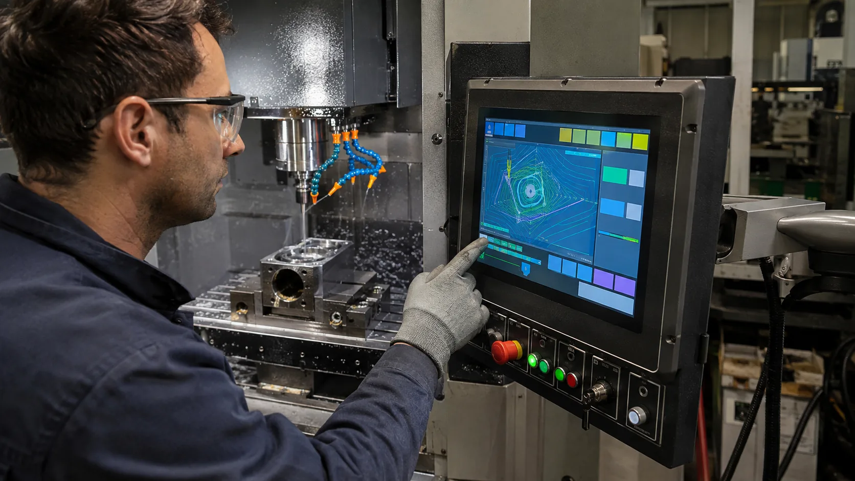 Final HMI validation should include real machining screens, gloves, lighting, coolant exposure, and operator positions.
For a long-lived CNC platform, review supply continuity as carefully as screen appearance. Ask about module lifecycle, change notification, controller availability, qualified alternatives, and optical variants. These details reduce redesign risk when a machine remains in production and service for years.
Practical RFQ Checklist
Include the machine type, mounting drawing, viewing distance, display size, active area, resolution, brightness, viewing-angle requirement, touch type, cover lens, interface, controller constraints, operating temperature, cleaning method, annual quantity, and lifecycle target. Screenshots of the real HMI and photos of the target installation help identify problems early.
Sunshine Display supports industrial TFT LCD modules and touch display assemblies for OEM equipment. Contact Sunshine Display to discuss a CNC control panel display project.
FAQ
What TFT LCD size is suitable for a CNC control panel?
The right size depends on the control interface, viewing distance, enclosure opening, and whether the screen must show toolpaths, alarms, offsets, and service pages together.
Can projected capacitive touch work with CNC gloves?
It can, but the touch sensor, cover glass, controller tuning, glove material, moisture, and grounding should be tested with the actual use case before release.
Why does CNC electrical noise matter to an LCD module?
Drives, motors, contactors, and long cable runs can affect signal quality and touch stability. Power sequencing, grounding, shielding, and routing need system-level validation.