An operator panel gives technicians a clear view of inspection status without placing the display in the camera’s optical path.
When a machine-vision cell flags a part, the operator often needs to answer two questions quickly: what did the camera find, and what should happen next? The camera image may be confined to an engineering screen, while a production operator needs a concise pass, reject, or review state at the station. The TFT LCD is the bridge between inspection logic and the person responsible for clearing the next step.
For OEM teams, selecting that display is not just a matter of matching a diagonal to the control-box cutout. The panel must remain readable at its installed angle, fit around camera and lighting hardware, and present results without encouraging an unsafe reach into a guarded area. These decisions are easier to settle before the station enclosure and operator workflow are frozen.
Separate the Operator View from the Inspection Image
Engineers may need magnified regions, overlays, and parameter controls during setup. Production staff need a large state indicator, part identifier, and a clear route for handling an exception. Putting every engineering control on the production screen can make routine decisions harder to see.
Map the screen states to station events: idle, ready, inspection running, pass, reject, and result unavailable. Decide what remains visible if camera communication is lost or no part is present. Keep physical reset or acknowledge controls distinct from routine navigation.
For remote quality review, the TFT may need to show a trend or a selected image. For a compact cell, a clear summary can be enough. Write down which information must be understood at a glance, which belongs on a maintenance page, and which stays in the engineering setup tool. That hierarchy helps determine whether a standard TFT module is adequate or whether the application needs a wider viewing cone or a different optical treatment. Sunshine’s standard TFT LCD modules provide a starting point for matching panel format to the station layout.
Place the Panel Around the Camera, Light, and Guarding
The camera, lens, illumination, and workpiece determine where the display can go. A panel placed too close to a ring light may collect glare. A screen mounted on the same swing arm as the camera can move out of the operator’s natural sightline. A recessed location may protect the glass but make touch targets awkward to reach.
Review the assembly from the operator position, including when a tote or fixture partly blocks the view. Check the display with its actual front window, bezel depth, service film if used, and overhead lighting. A bare module cannot reveal reflections from a cover lens or shadows from a deep bezel.
A wide viewing angle can help when operators approach from more than one side of a cell. In that case, compare the IPS TFT LCD options using the interface’s real colors and brightness levels. Review red and green status cues, thin graph lines, and any camera thumbnail at the installation angle—not only a bright full-screen test pattern. Color should support the decision; it should not be the only indication of a reject or fault.
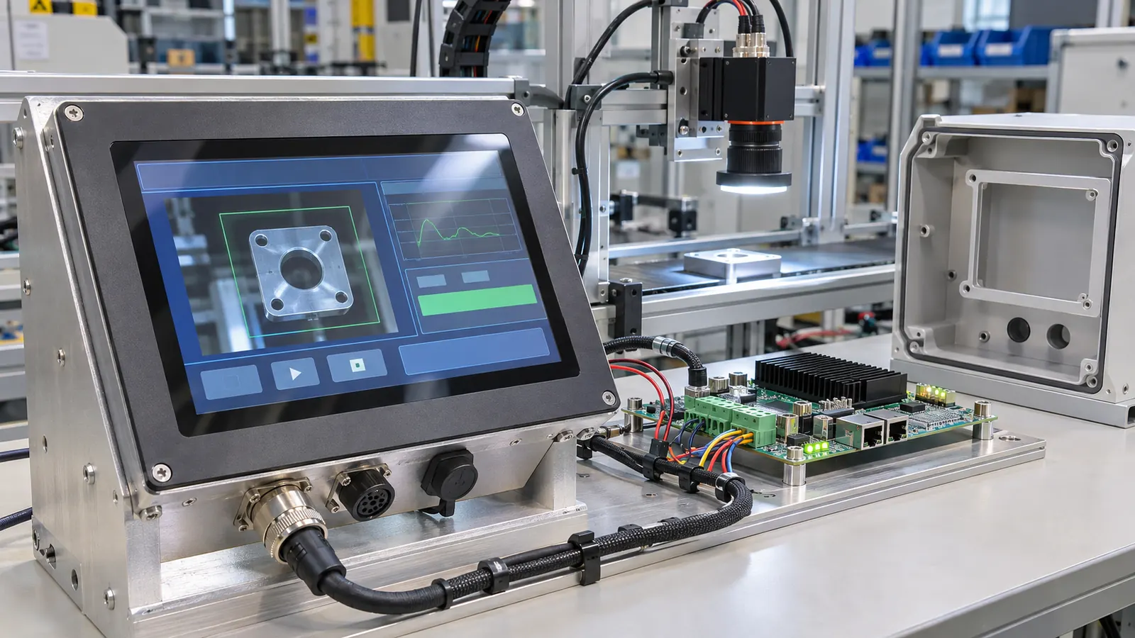 The module, host electronics, enclosure mockup, and inspection camera should be reviewed as one station design.
Keep Display Hardware Out of the Optical Path
Machine-vision performance depends on stable camera geometry and controlled lighting. The operator display should not obstruct the lens, reflect illumination back into the camera, or force a camera relocation late in integration. Model the display and its bezel in the station layout alongside the camera field of view, cable bend radius, lighting adjustment range, and access needed to clean the lens.
This does not require the display to be physically far away. It requires a deliberate location and a validation check. With the intended workpiece in place, run representative captures while changing screen brightness and viewing the station from normal operator positions. Look for unwanted reflections, accidental shadows, and glare on the protective cover. Record the result so later changes to the panel, lens, or lighting can be assessed against the same setup.
The display’s electrical integration also deserves an early bench review. Confirm the selected interface and connector arrangement with the host controller, check startup sequencing, and observe behavior when the station is switched or reset. Route display and camera cables so service work does not disturb lens alignment or illumination wiring. Avoid assuming that a module which operates on a desk will behave identically after installation beside switching loads and long harnesses.
Choose Touch Only for Tasks That Benefit from It
Touch can make recipe selection and maintenance menus convenient, but a production cell may already have physical start, stop, reset, or acknowledge controls. Decide which tasks are frequent enough to justify touch and which need a dedicated control that can be found without looking. Keep touch targets large enough for the expected gloves and leave room around critical actions to reduce accidental selections.
If touch is part of the plan, test the complete stack: sensor, cover glass, adhesive, bezel, grounding, and host software. Validate it with the actual glove types, cleaning routine, and screen angle. A touch panel that works before the front window is fitted may behave differently after the mechanical stack changes. Sunshine’s capacitive-touch TFT modules can be compared against that assembly brief.
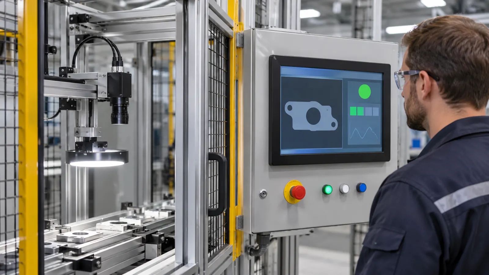 The installed position determines whether status, controls, service access, and camera alignment work together.
Validate the Station, Not a Screenshot
Build a representative station mockup before releasing the production enclosure. It should include the display, intended cover, controller, camera, illumination, guards, cable routes, and a sample workpiece. Ask operators to perform normal production and exception handling without coaching. Note where they stand, whether they can read a reject reason, and how they recover after a missed trigger or unavailable result.
Repeat the review under the lighting and environmental conditions the station will actually encounter. If the cell is near a loading door or in an unconditioned area, compare the planned operating range with the display assembly and enclosure design. Sunshine’s wide-temperature TFT LCD modules may be relevant where temperature exposure is part of the equipment brief; confirm the required range for the complete product rather than relying on a module label alone.
Keep a short approval record: approved viewing positions, UI states, display brightness setting, cover construction, touch behavior, camera reflection observations, and cable arrangement. It gives engineering, production, and service teams a common reference when a supplier change or enclosure revision is proposed.
Put the Integration Details in the RFQ
A useful request for quotation includes the active display area and outline, interface, target viewing positions, brightness needs, cover and touch plan, operating conditions, annual volume, lifecycle expectation, and sample schedule. Attach the enclosure drawing and describe what operators must see during pass, reject, and fault states. Ask suppliers to identify any unanswered mechanical or optical questions before sample approval.
Sunshine Display works with industrial and OEM display applications. If you are developing a machine-vision station, share the panel layout, host interface, viewing conditions, and validation plan through the contact page.