A panel display for a power quality analyzer has to remain readable while the instrument is connected, carried, and used at the point of measurement.
Industrial power quality analyzers sit at an awkward intersection of measurement engineering and field usability. They may be carried to a cabinet during commissioning, left at a substation for a recording campaign, or built into a permanent monitoring enclosure. In every case, the operator needs to interpret electrical conditions quickly: phase balance, harmonics, disturbances, demand trends, alarms, and recording state. The TFT LCD module is therefore not decoration. It is the part of the instrument that turns captured data into a reliable decision under real lighting, time pressure, and electrical noise.
For OEM teams, a suitable display starts with the measurement task rather than a familiar screen diagonal. A small portable analyzer and a fixed cabinet recorder can share an interface concept while needing very different optical stacks, mechanics, operating ranges, and service plans. The useful goal is a display assembly that supports accurate use throughout the product's lifecycle—not simply an attractive screen in a prototype.
Define the Reading Task Before Selecting a Panel
First map the moments when someone looks at the analyzer. A commissioning technician may stand close to confirm lead connections and waveform stability. A maintenance engineer may read an alarm state from an angle in a bright electrical room. A control-panel user may need a clear trend view through a protective window. For each moment, specify distance, angle, expected ambient light, required data density, color cues, and the consequence of an incorrect interpretation.
That brief establishes whether the module needs high brightness, a wider viewing cone, particular contrast behavior, or a front-lens treatment. It also keeps UI ambition in proportion: a compact live waveform, a few unambiguous status indicators, and a well-prioritized alarm can be more valuable than squeezing every parameter onto one screen. The Sunshine Display product range is a useful starting point for comparing module formats against the actual analyzer enclosure and duty cycle.
Match the Optical Stack to the Installation
The same TFT can look excellent on an indoor bench yet underperform once placed behind a cover lens in a cabinet door. Reflections from overhead luminaires, a recessed bezel, polarized safety glasses, fingerprints, and the angle of the operator all change the perceived image. Evaluate the display with the intended lens, gasket, bezel depth, and anti-glare treatment, rather than approving a bare panel under ideal light.
For interfaces where an operator may approach from either side of a cabinet, IPS TFT LCD modules can be relevant because viewing behavior matters as much as headline resolution. Confirm the visual performance using representative waveform colors, alarm states, and dimmed historical plots. A test image with legible product text tells little about whether a technician can distinguish a transient event from a normal trace at the required viewing angle.
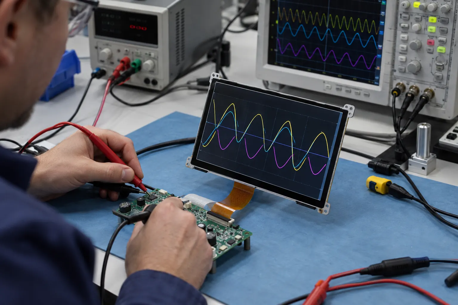 An early bench setup makes it easier to verify the display, controller, power rails, and signal interface as one engineering system.
Treat Interface and Power as Design Inputs
Power quality instruments already contain sensitive analog measurement paths, isolated inputs, power supplies, and communications. The display subsystem needs a planned place in that architecture. Review interface selection, connector retention, cable routing, grounding, backlight supply behavior, start-up sequencing, and recovery after a brownout. A screen that wakes inconsistently after an auxiliary supply dip can erode trust even if the meter continues logging correctly.
Bring the proposed TFT module, controller board, and final harness to the validation bench early. Look for electromagnetic interaction during representative capture modes, switching events, and backlight changes. Define the boot presentation and what the user sees when a record is incomplete or a sensor channel is unavailable. These decisions connect firmware, UI, and display hardware, preventing a late enclosure change from becoming a field-service problem.
Make Touch and Controls Work With PPE
An analyzer used in an electrical room is often operated with gloves, after a long shift, or in cramped access space. A capacitive touch surface can be appropriate, but only after the cover glass thickness, glove behavior, moisture exposure, and nearby conductive frame are validated in the finished assembly. Teams planning touch interaction can review capacitive touch TFT LCD options alongside their own touch-tuning and ESD plan.
Do not assume touch replaces physical controls. Dedicated keys, a rotary input, or clearly separated alarm acknowledgement can be safer for a frequent or time-critical action. Check the complete sequence with technicians: opening the cabinet, reading the display, selecting a record, acknowledging a message, and leaving the enclosure secure. The right interface reduces uncertainty without demanding two-handed precision in front of energized equipment.
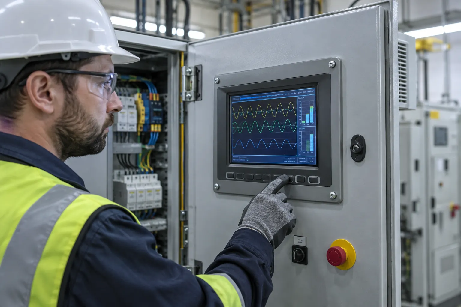 The final enclosure changes viewing angle, reflections, touch behavior, and service access—issues that a bare module cannot answer alone.
Validate the Assembly Across Its Real Environment
Temperature, condensation risk, vibration during transport, dust, and long operating hours can expose gaps between a panel specification and the finished analyzer. Validate the display assembly—not only the module—through the conditions it will experience. Include the front lens, adhesive or gasket, mounting features, backlight setting, cable strain relief, and enclosure heat path.
If the analyzer will serve outdoor-adjacent switchgear, utility vehicles, or unconditioned rooms, compare the intended operating profile with wide-temperature TFT LCD modules. The display should be assessed together with its power and thermal design; brightness, internal heat, and enclosure sealing each affect the practical operating margin. Planning that stack early is usually less expensive than adjusting an established housing after samples arrive.
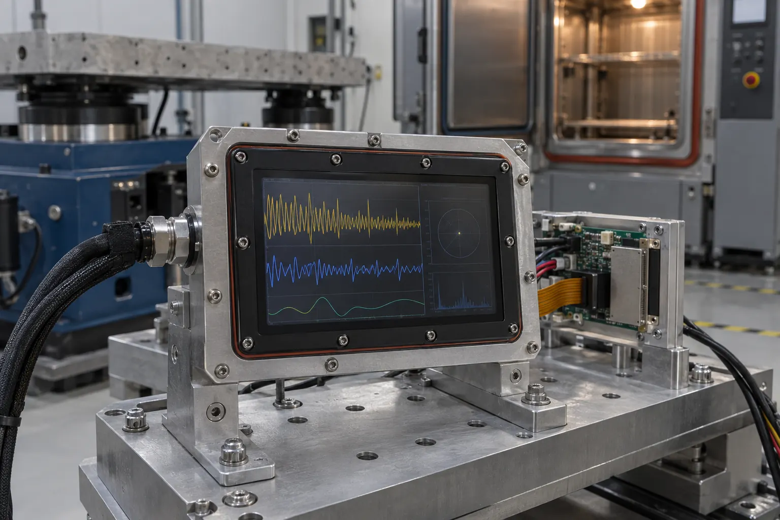 Fixture testing reveals how a display assembly, front lens, sealing strategy, harness, and mounting hardware behave together.
Build a Procurement Brief That Supports the Product Lifecycle
A useful RFQ goes beyond diagonal and resolution. Include active area, outline, interface, brightness target, viewing direction, touch or key requirements, front-lens construction, operating range, expected lifecycle, annual volume, regulatory constraints, and sample-validation schedule. State whether the product will be portable, panel mounted, or both. This gives the display supplier the context to flag mechanical or optical risks before a design is locked.
Before releasing production tooling, run a sample build using the target enclosure and representative firmware. Capture readability observations, boot and recovery behavior, touch results, thermal data, EMC findings, and replacement-service time. Sunshine Display can help OEM teams review a TFT module and integration brief for industrial instruments; contact the team with the operating environment, enclosure concept, and validation priorities.
The strongest display choice for a power quality analyzer is the one that keeps electrical information understandable when it matters, while remaining practical to source, manufacture, validate, and service.