When a motor drive reports a trip, an operator should not have to decode a crowded screen while standing at a cabinet. They need to see what changed, decide whether it is safe to reset, and make the next adjustment without losing the production context. That puts the display module, graphics, keys, lens, and enclosure at the center of the operator interface—not at the end of the mechanical design.
Start sample review with the drive panel, controls, and enclosure that operators will actually use.
Begin with the decisions at the panel
List the actions an operator actually takes at the drive. They may compare a running value with a setpoint, switch between local and remote control, identify an alarm, view a parameter group, or confirm that a stop command was accepted. Each task sets a different requirement for data density, contrast, button placement, and viewing distance.
Use the production screens when evaluating candidates. A colorful demonstration screen does not show whether a small fault code, a unit symbol, or a highlighted parameter remains legible through the planned front lens. Put the interface into its intended enclosure and ask reviewers to find a running state, a changed setting, and an alarm acknowledgment from their normal standing position. The time needed to locate each item can reveal that a seemingly adequate layout is too dense.
The installation also affects the module choice. A standard TFT LCD module can suit a panel with a controlled viewing position. Where a control cabinet is read from the side, from a raised platform, or by different-height operators, compare real samples with an IPS TFT LCD module. View-angle behavior should be checked with the actual color palette and text sizes, not inferred from the panel name.
Keep the operating state obvious
A drive interface often has more information available than an operator should see at once. Separate the screen used to run the machine from screens used for setup and service. The running view should make the present state understandable at a glance: operating mode, a meaningful process value, direction where relevant, and a clear indication of an attention condition. Put secondary configuration behind a deliberate navigation step rather than shrinking every field until it technically fits.
Do not make a safety-relevant distinction depend only on color. Pair a color change with a label, shape, position, or persistent state indicator. This matters when the panel is viewed under uneven cabinet lighting, through a scratched lens, or by an operator who is reading quickly. Test dimmed, angled, and reflection-prone views during the UI review.
Physical controls still deserve attention. A dedicated stop or acknowledge action can be easier to use than a precise touch target when gloves, vibration, or limited access are involved. If a touch interface is appropriate, assess a capacitive-touch TFT LCD module with the intended cover lens, grounding plan, and nearby metalwork. A bare sensor test does not prove the finished assembly will respond as expected.
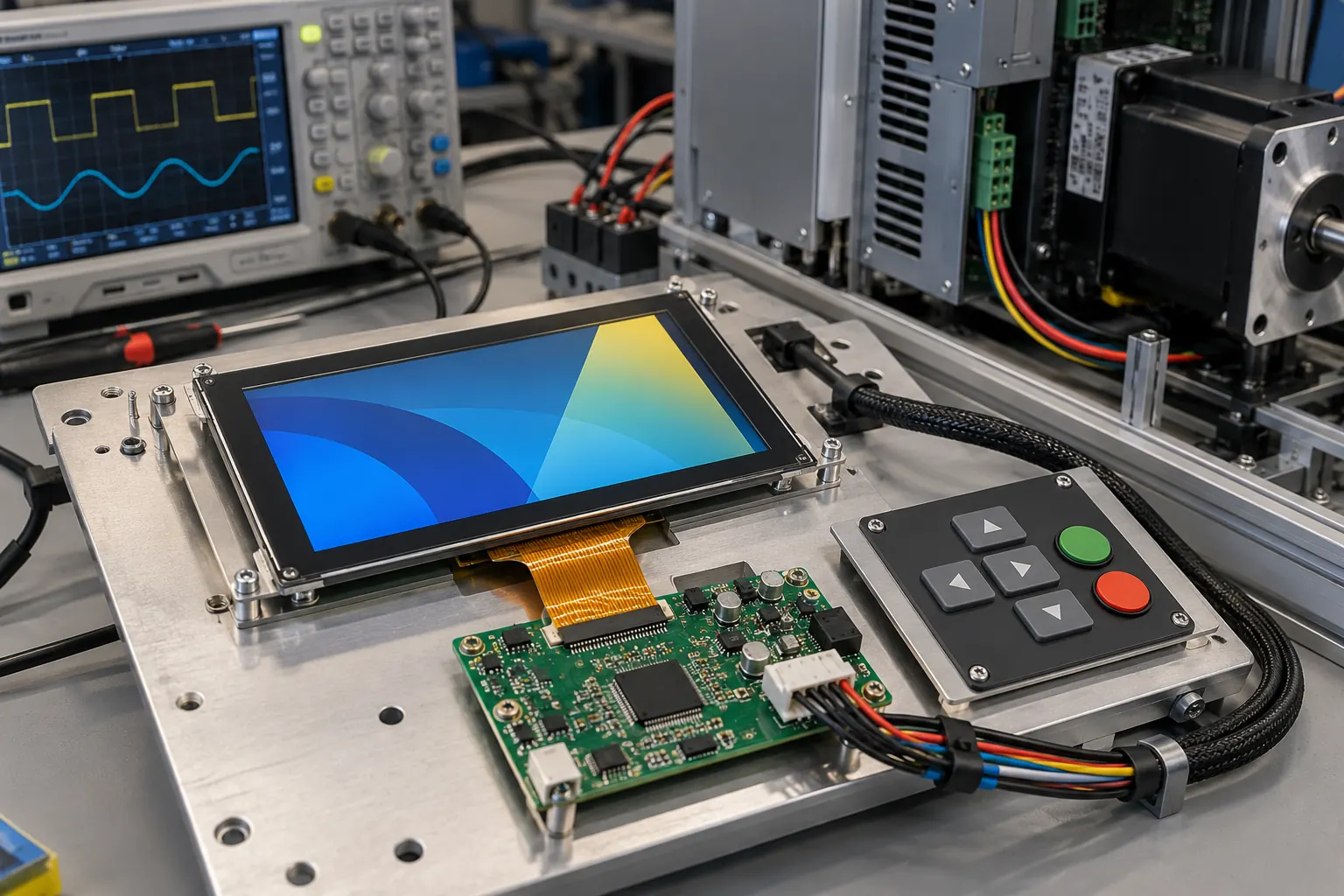 Bring the display, host electronics, front panel, and representative software together early in the build.
Design the display into the drive architecture
The display and its backlight draw power, exchange data with the controller, and add cables or connectors inside an electrically busy product. Review those items alongside the drive electronics. Consider startup order, what the panel shows after a supply interruption, connector retention, harness routing, and how the controller reports a communication problem. A blank or misleading screen during recovery can turn a manageable interruption into a service call.
Build an early bench assembly with the proposed display, host board, front panel, and representative software. Exercise the interface while the drive controller performs the conditions relevant to the product design. The purpose is not to claim a certification result from a prototype; it is to expose integration questions while cable lengths, bezel openings, and software behavior can still be changed.
Ask practical service questions at the same time. Can a technician reach the display connector after the panel is mounted? Does the harness have strain relief? Can the lens, key mat, and display be aligned without creating pressure points? If the panel needs replacement, determine whether it is exchanged as a module, a complete front assembly, or a service kit. These choices affect the mechanical drawing, spares strategy, and field instructions.
Validate the complete front panel
The display will be seen through more than its own cover glass. A cabinet window, gasket, printed border, recessed bezel, and the ambient light around the machine all change the installed image. Review the assembly under likely lighting, including overhead fixtures and sunlight spill from nearby doors. Look from the positions available to the operator rather than only square-on at a bench.
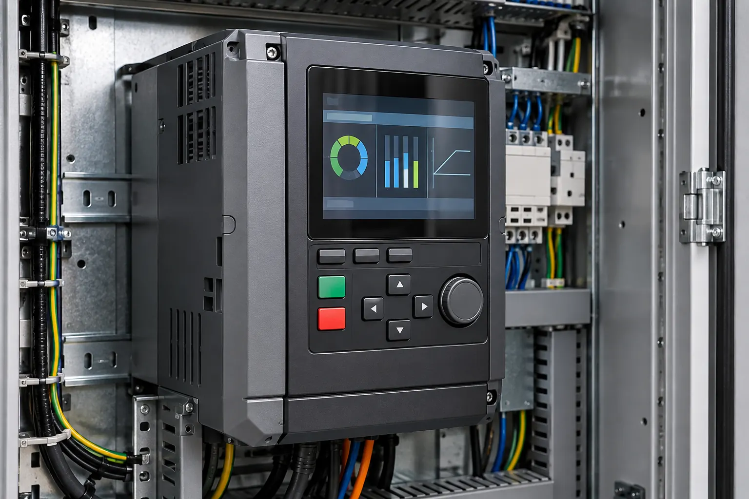 Validate viewing, mounting, and service access with the full front-panel assembly in place.
For installations near unconditioned production areas, vehicle-mounted equipment, or outdoor-adjacent machinery, compare the expected environment with candidate wide-temperature TFT LCD modules. The practical operating margin comes from the complete design: enclosure heat, backlight use, sealing, mounting, and power behavior all matter. Avoid treating one line in a module datasheet as a substitute for assembly-level validation.
Write down the configuration being approved: module part number, display orientation, interface, backlight setting, lens material and finish, bezel geometry, software revision, and the sample screens used for review. Capture the conditions that exposed reflections or weak contrast. A record like this lets engineering, purchasing, and quality teams compare a later sample with the one that was actually accepted.
Turn the sample review into a purchase-ready brief
An OEM RFQ should explain the operator task as well as the panel dimensions. Include active area, outline limits, interface preference, viewing direction, optical requirements, touch or key strategy, environment, expected product lifecycle, annual demand, and the intended validation build. A clear brief gives the display supplier an opportunity to identify risks before tooling and firmware are fixed.
Before volume release, assemble representative units using the intended lens and mounting approach. Repeat the running-state, alarm, navigation, startup, and service-access checks. Retest after a material, controller, panel, or bezel change; individual parts may appear equivalent while the installed readability changes.
Sunshine Display supplies industrial TFT LCD modules for OEM equipment. Share the enclosure concept, representative screens, and operating conditions through the contact page to discuss suitable display candidates for a motor drive panel evaluation.