A display can look clear on the bench and become difficult to read after the enclosure window is fitted. The window adds another surface, changes reflections, and can put the image at a different apparent depth. If touch is part of the panel, the cover lens and sensor introduce another set of integration choices. Review the complete optical stack in the environment where operators will use it.
Assess the installed display through the same window and bezel planned for the machine.
Start with the installed view
Write down where the operator stands, what they need to read, and what light reaches the panel. A machine beside a factory window has a different problem from an indoor instrument viewed under overhead fixtures. Include the expected viewing distance, the range of operator heights, and whether the display is read while standing, seated, or moving past it.
Then identify the actual content. Large status fields and a few controls place different demands on a display than dense tables, fine traces, or small text. Bring representative screens to the sample review. A blank white image or a colorful demo screen cannot show whether the smallest labels, warning states, and low-contrast details remain legible through the production window.
This review also helps choose the panel technology. A standard TFT LCD module may suit a fixed viewing position and a controlled indoor environment. Where operators approach from the side or the screen is mounted at an angle, compare the intended panel with an IPS TFT LCD option using the same content and viewing positions. Compare actual candidate modules; do not assume a technology label alone settles the question.
Treat the cover as part of the display
The protective window is not just a mechanical cover. Its material, thickness, surface finish, coatings, tint, shape, and spacing from the display can change what the operator sees. Reflections can come from the outer surface and from interfaces within the stack. A gap between layers may make those reflections more noticeable in some lighting conditions, while bonding can change the optical path and assembly requirements. Neither approach should be selected from a slogan: evaluate the actual module, window, adhesive or spacer, and enclosure together.
Use production-intent samples where possible. Keep the window’s finish and tint consistent with the planned part, and include printed borders or masks if the design uses them. Check that the display active area remains visible through the opening, including corners and edges. A housing lip that seems minor in a drawing can obscure content from an off-axis position.
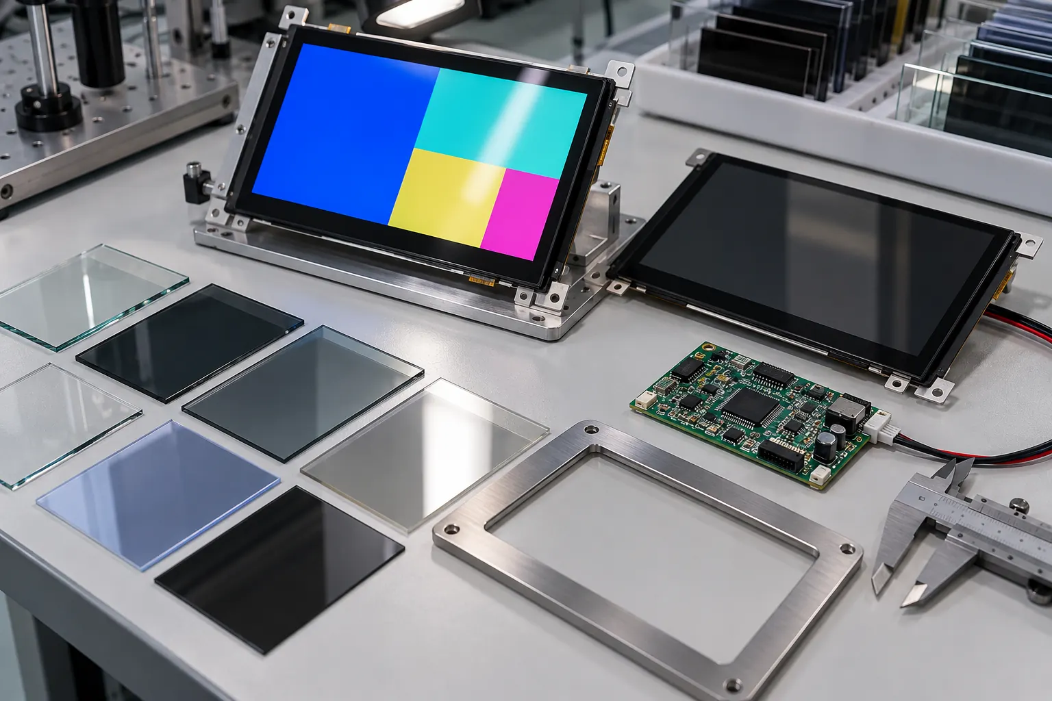 Compare window samples under the lighting and viewing positions used by operators.
Look at the sample with the room lights on and with likely light sources reflected in the window. Move to the operator’s normal positions instead of holding the assembly square to your face. Check for distracting reflections, washed-out colors, reduced contrast, and reflections of nearby machinery or clothing. Record the lighting and viewing position that produced each observation so later comparisons are fair.
Review touch, graphics, and assembly together
If the product uses projected capacitive touch, include the final cover lens and the intended sensor arrangement in the review. Cover thickness, air gap or bonding design, grounding, and the surrounding enclosure can all affect the assembled interface. Test taps and gestures across the usable area with the gloves, moisture conditions, or operator technique expected in the application. Confirm that the optical sample is also the touch sample; a separate bare module does not answer how the finished panel will feel.
Check display content for the viewing angle and reflections you observed. Avoid relying only on color distinctions for critical states. Use clear labels, adequate spacing, and contrast between a status and its background. If operators need to read a value while standing to one side, show that exact screen from that position. A capacitive-touch TFT module can be one candidate, but the complete lens, sensor, controller, and enclosure need assessment as a system.
There is also a mechanical question: can the stack be assembled repeatedly without uneven pressure, trapped dust, or visible misalignment? Define how the window is located, how the module is supported, and how the assembly is opened for service. Ask the engineering team to inspect cable clearance and connector access after the window and bezel are installed. If a bonded stack is being considered, clarify which party supplies each layer and owns process control, rework, and replacement.
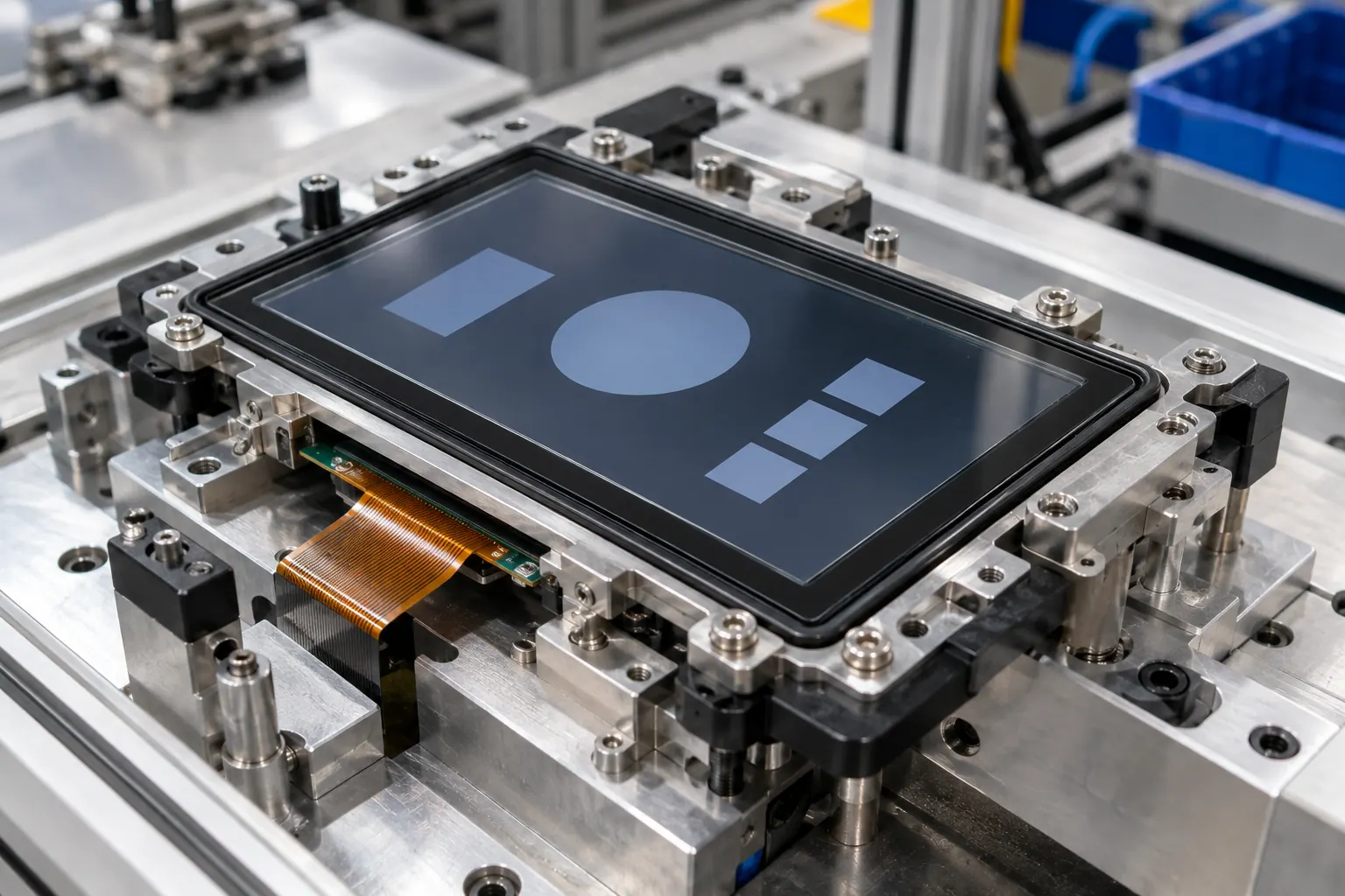 Review the cover lens, touch system, and display as one assembled interface.
Make sample approval repeatable
For an OEM decision, record the module part number, window material and finish, stack spacing or bonding method, bezel opening, touch configuration, and representative content revision. Note the test positions and lighting conditions. These details make it possible to compare a revised sample with the approved one and to identify which change affected readability.
Ask several people who resemble the intended operators to read the same prompts from the same positions. Have them find a status, distinguish two operating states, and activate the controls they would use on the machine. This is a practical design review, not a formal measurement or certification. If the application needs quantified optical acceptance limits, define the measurement method and conditions with the responsible engineering team before approving production.
Retest when a supplier changes the window finish, adhesive, tint, panel, or bezel geometry. Even when each component seems similar, the assembled result can change. Preserve an approved reference unit and its configuration record so purchasing, quality, and engineering teams can review later samples against the same baseline.
Choose from the complete assembly
The right TFT module is the one that works with the real window, graphics, touch method, viewing positions, and service plan. A display that wins a bare-panel comparison may not be the best choice once those parts are assembled. Bring the enclosure drawing, candidate content, and intended lighting conditions into the sample stage, and settle open optical and mechanical questions before tooling or volume purchasing.
Sunshine Display supplies industrial TFT LCD modules and supports OEM selection. Share your enclosure details and viewing requirements through the contact page to discuss suitable candidates for evaluation.