A round TFT LCD can give an industrial instrument a compact, focused interface, but the round outline can conceal rectangular realities behind the front panel. The visible circle, active pixel area, module outline, mounting features, FPC exit, and connector space may all follow different geometry. A successful round TFT integration begins with those boundaries drawn separately.
Review the circular visible area with the actual bezel, not just a module drawing.
Define the visible circle before the housing is frozen
Start with the operator’s visual field. The bezel opening should reveal the intended active image without clipping critical content at the edge or exposing an inactive border that was not part of the front-panel design. Use representative screens in the sample: a circular gauge, a status ring, warnings near the edge, and fine labels. A centered demo image can make a marginal opening look acceptable while a real status layout reveals lost pixels or poor spacing.
Compare candidate formats from the Sunshine Display product range against the actual enclosure drawing. Record the visible area, active area, outline, mounting plane, and front-lens stack independently. That simple discipline prevents a nominal diameter from becoming the only mechanical requirement.
Keep cable direction inside the layout decision
Round modules are often selected for the front appearance first and the FPC route second. That sequence can produce a cable that leaves toward a rib, latch, battery compartment, or sharp bend. Decide orientation with the FPC and connector in view. Rotate the sample through every plausible mounting position and check whether the cable can reach the host board with suitable clearance and strain relief.
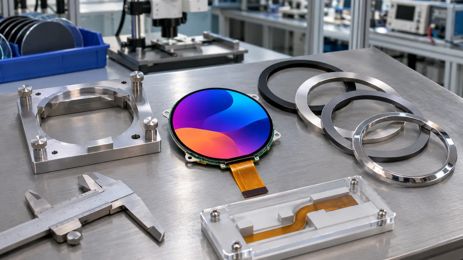 Check cutout, mounting ring, active area, and cable space in one sample build.
Check the cable route after the bezel, lens, and rear support are assembled. It must not be pinched by a locating feature or pushed against an edge by the installed display. If the module needs replacement, inspect whether the connector is reachable without removing unrelated equipment. These are assembly and service questions, not details to defer to a drawing note.
Design content for the round field
A circular screen is not simply a square user interface with cropped corners. Reserve the center for the information that must be recognized first and keep critical labels away from the extreme edge. Use adequate contrast and do not make a warning depend on color alone. For a panel read from more than one approach angle, evaluate optical behavior using the final graphics; an IPS TFT LCD option may be relevant depending on the equipment layout.
 Confirm FPC clearance and connector service access after enclosure assembly.
A round display succeeds when its mechanical boundaries, cable route, service access, and visual hierarchy have all been reviewed in the complete assembly. The front circle is the beginning of the design discussion, not the end.
Check the circular edge under production variation
The most noticeable defect on a round panel is often at the edge: a clipped symbol, an uneven mask width, a crescent of inactive glass, or an off-center image. Review the assembly at the limits of the mechanical tolerance, not just at the nominal position. Use edge-adjacent content during the check and inspect the front under the same lighting that will reach the instrument.
The mounting ring or rear support should locate the display without distorting it. If the front window is used to force the module into place, temperature changes and screw loading may create inconsistent pressure. Give the stack a defined load path and make sure the round module can be removed without scraping the active surface or stressing its cable.
Align the firmware coordinate system
The physical orientation, controller coordinate system, touch orientation if present, and graphics rotation need one documented agreement. A sample can appear correct during a quick bring-up while a later firmware rotation moves critical labels toward the edge. Include orientation in the software-to-mechanics review and keep a screen capture with the approved build.
Validate the finished assembly
Bench approval should not be the final decision. Build a sample with the intended module, controller, cable, mounting method, front lens or bezel, and representative firmware. Check the screen from the positions available to operators, then repeat the checks after a restart, a power interruption, and a service-access exercise. Record what was tested rather than relying on a general impression that the display looked acceptable.
Document the part number, active area, outline, interface, display orientation, host software revision, backlight or drive setting, mounting details, and screen examples used during the review. When a display, enclosure, controller, or cable changes later, that record gives engineering and purchasing teams a meaningful baseline for deciding whether another sample review is needed.
Make the RFQ support the product lifecycle
An OEM request should describe the operator task and equipment environment alongside size and resolution. Include available space, viewing position, interface, expected operating conditions, service access, annual demand, lifecycle expectations, and the validation build. A clear brief helps identify mechanical and electrical questions before a housing or firmware is locked. Sunshine Display can help teams compare industrial display modules against an enclosure and integration plan through the contact page.
Before releasing the design, define the acceptance sample and the evidence that accompanies it. That can include the module identification, installation drawing, image or screen set, test conditions, observations, and the responsible reviewer. Keep the approved reference assembly available where practical. It is often the fastest way to understand whether a later change in material, controller, cable, display orientation, or enclosure has altered the result that the team originally accepted.
Avoid treating a display as a cosmetic item after the first prototype works. The screen is an operator interface, an electrical load, a mechanical component, and a service item at the same time. A short cross-functional review between mechanical, electrical, firmware, quality, and purchasing teams can expose a gap before it becomes a field issue.