COG and COB describe different ways of organizing display electronics, but neither abbreviation decides a product selection on its own. The better choice depends on what the equipment needs: available depth and outline, display format, host connection, mounting support, cable route, service strategy, and the way the module is protected inside the enclosure.
Compare the actual glass, PCB, connector, and mounting features instead of abbreviations alone.
Look at the module as a mechanical part
A chip-on-glass approach places the driver directly on the glass, while chip-on-board places electronics on a board associated with the display assembly. The visible result may look similar from the front, but the rear-side geometry, connection method, support requirements, and clearances can differ. Inspect the real module rather than comparing only a catalog sketch.
Place the candidate against the mounting features in the equipment. Check support locations, pressure points, connector direction, and the space required for a cable or flex. A compact module may save front-panel space but still need careful protection against uneven mounting force. A board-backed module may offer different mounting references while asking for more depth or a different connector approach.
Match the electrical connection to the host
The controller interface, supply arrangement, signal route, and power-up behavior should be reviewed with the actual host architecture. Define how the module connects, where the cable is retained, and how a technician would inspect or replace the assembly. Do not treat a successful bench connection with short loose wires as proof that the final enclosure will have the same margin.
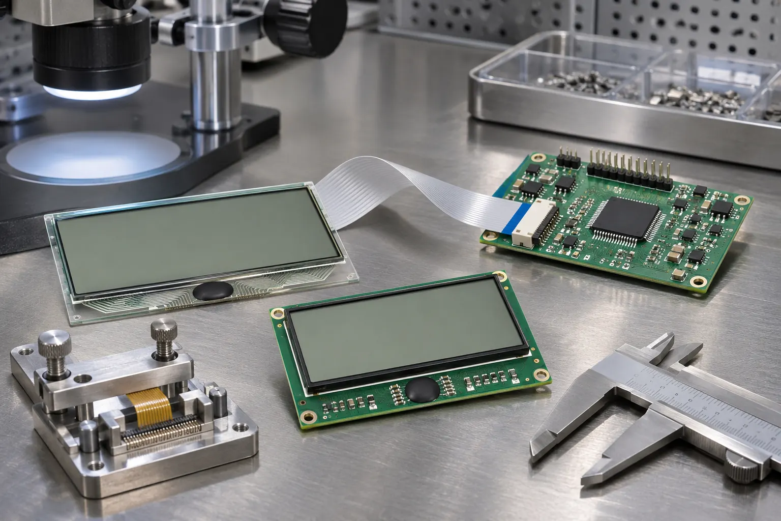 Review controller connection, cable routing, and module support with representative samples.
Use the required content in the evaluation. A fixed character-oriented readout, a simple segment display, and a graphic screen place different demands on the controller and interface. The Sunshine Display product range can provide a starting point for comparing industrial module categories, but the final choice should come from the equipment task and integration sample.
Plan for support, protection, and replacement
A display needs a defined support strategy. Consider the front window or bezel, rear support, gasket, locating features, connector relief, and the access required for a replacement. A module should not be forced into position by a lens or clamped unevenly by fasteners. Review the final stack with a sample build and confirm that the cable does not become the only element carrying mechanical load.
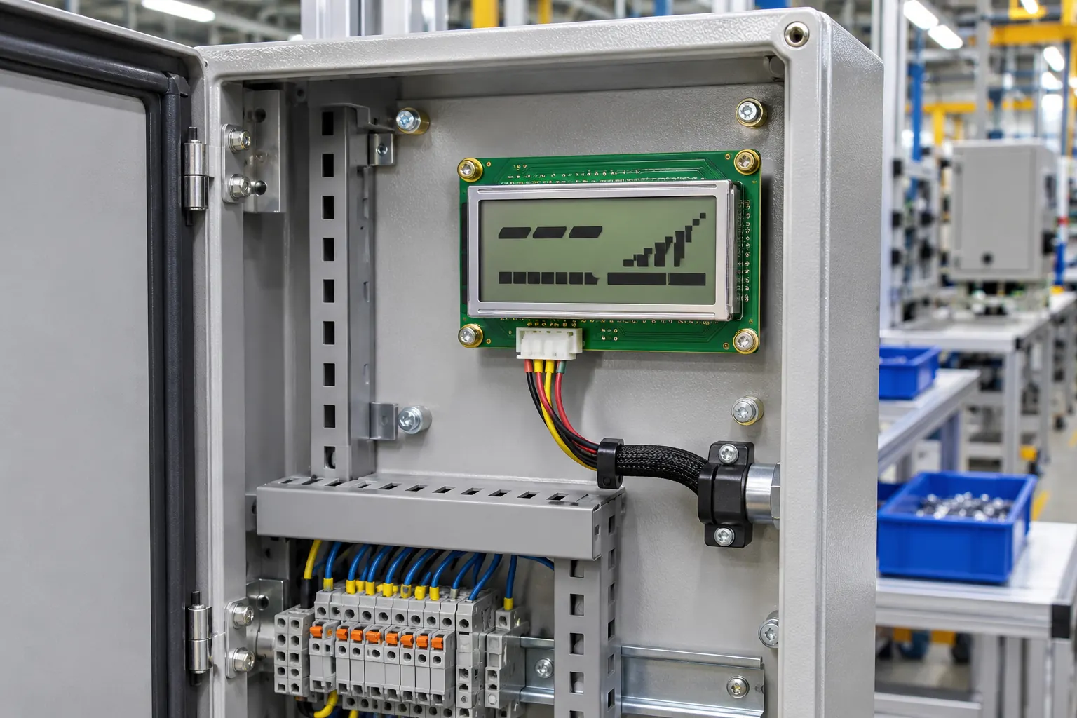 Check the installed module for mechanical support and connector service access.
When replacing an older module, verify more than the front dimensions. Check active area, outline, viewing direction, interface, controller compatibility, connector location, backlight or drive requirements, mounting points, and software behavior. A similar-looking module may create a different electrical or mechanical integration task.
Compare the interfaces that create the integration work
Ask where the intelligence is located, how it is connected, and what the host must provide. The practical difference can include cable type, connector type, signal timing, mechanical protection, and the way an assembly is supported. Bring the selected module to the electrical review with the proposed host board and intended harness rather than deciding from a front-view photograph.
For older products, confirm what the existing software assumes about initialization, data formatting, contrast control, and interface timing. A replacement project often fails when a visually similar module requires a different electrical sequence or a different physical cable route. Capture those dependencies in the change-control record before declaring a substitute acceptable.
Let the service model influence the choice
Some equipment is repaired by swapping a front assembly, while other products need a display-only replacement. Define which approach applies and make sure the module and connector can support it. A clear service model helps avoid a compact design that is difficult to repair or a robust module that does not fit the available maintenance time.
Validate the finished assembly
Bench approval should not be the final decision. Build a sample with the intended module, controller, cable, mounting method, front lens or bezel, and representative firmware. Check the screen from the positions available to operators, then repeat the checks after a restart, a power interruption, and a service-access exercise. Record what was tested rather than relying on a general impression that the display looked acceptable.
Document the part number, active area, outline, interface, display orientation, host software revision, backlight or drive setting, mounting details, and screen examples used during the review. When a display, enclosure, controller, or cable changes later, that record gives engineering and purchasing teams a meaningful baseline for deciding whether another sample review is needed.
Make the RFQ support the product lifecycle
An OEM request should describe the operator task and equipment environment alongside size and resolution. Include available space, viewing position, interface, expected operating conditions, service access, annual demand, lifecycle expectations, and the validation build. A clear brief helps identify mechanical and electrical questions before a housing or firmware is locked. Sunshine Display can help teams compare industrial display modules against an enclosure and integration plan through the contact page.
Before releasing the design, define the acceptance sample and the evidence that accompanies it. That can include the module identification, installation drawing, image or screen set, test conditions, observations, and the responsible reviewer. Keep the approved reference assembly available where practical. It is often the fastest way to understand whether a later change in material, controller, cable, display orientation, or enclosure has altered the result that the team originally accepted.
Avoid treating a display as a cosmetic item after the first prototype works. The screen is an operator interface, an electrical load, a mechanical component, and a service item at the same time. A short cross-functional review between mechanical, electrical, firmware, quality, and purchasing teams can expose a gap before it becomes a field issue.