LCD Module Voltage Compatibility Guide for OEM Designs
Voltage compatibility should be checked before connecting a TFT LCD module to the final mainboard.
Voltage compatibility is a practical but often underestimated issue in small TFT LCD module projects. A display may have the right size, resolution, interface, and brightness, but still fail during bring-up if the mainboard voltage, logic level, reset timing, or backlight driver does not match the module requirements.
For OEM buyers and engineers working with color LCD display modules under 32 inches, voltage review should happen before PCB layout and sample approval. It is especially important for handheld devices, medical instruments, industrial controllers, smart home panels, meters, POS terminals, and battery-powered equipment.
If you are comparing display options, start from Sunshine Display's LCD display module product range and review electrical compatibility together with mechanical and optical requirements.
1. Separate Display Power From Logic Signals
Many LCD modules have more than one electrical requirement. The module may need a panel supply voltage, logic interface voltage, backlight LED power, reset signal, standby signal, and sometimes a separate touch controller supply.
A common mistake is assuming that all pins use the same voltage. For example, the module may accept a 3.3 V supply but use 1.8 V logic signals, or the touch controller may require a different supply from the display driver. Some modules include onboard circuits, while others rely on the customer's mainboard.
Before connecting a sample, check the datasheet, pin assignment, absolute maximum ratings, recommended operating conditions, and backlight circuit notes.
2. Check 3.3 V and 1.8 V Logic Compatibility
Small TFT LCD modules may use SPI, RGB, MIPI DSI, MCU parallel, or other interfaces. The interface name does not tell the full voltage story. Signal voltage must match the processor or level shifting must be added.
If a 1.8 V display input is driven directly by a 3.3 V MCU, the module can be damaged. If a 3.3 V display input receives weak 1.8 V signals, the image may fail, flicker, or behave unpredictably.
When selecting standard TFT LCD modules, ask for logic voltage details early. For compact products, confirm whether the processor GPIO, display interface pins, reset, chip select, clock, and data lines all meet the display input requirements.
3. Validate Power Rails During Bring-Up
A bench power supply can make a display appear stable during early tests, but the final mainboard may behave differently. Power sequencing, voltage ripple, inrush current, reset timing, and standby behavior can affect display startup.
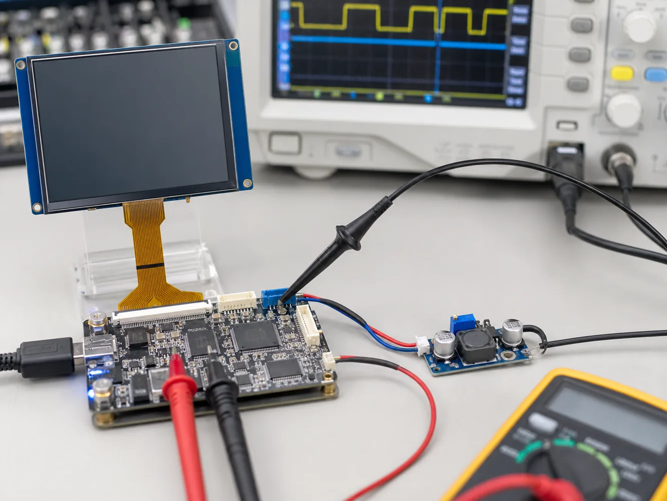 Display supply voltage, logic voltage, reset timing, and signal levels should match the processor board.
During bring-up, measure the real voltage on the LCD connector, not only at the regulator output. Check the display when the product powers on, wakes from sleep, enters standby, changes brightness, and communicates with the touch controller.
For high-volume projects, repeat the test across temperature, battery voltage range, and several display samples. This helps catch marginal designs before production.
4. Review Reset and Initialization Timing
LCD driver ICs usually need a defined reset and initialization sequence. If reset timing is wrong, the display may stay black, show noise, display incorrect color, or fail intermittently.
The reset pin voltage should match the module logic voltage. The firmware should follow the required delay after power-on, reset release, sleep-out command, display-on command, and backlight activation.
For displays with richer UI, such as IPS TFT LCD modules, proper initialization also affects color direction, scan direction, gamma, and display mode. Do not assume that a similar-looking module can use the same initialization table.
5. Treat Backlight Power as a Separate Design Topic
Backlight LEDs are usually current-driven. The LCD logic supply and the backlight supply are not the same thing. A display may operate its logic at 3.3 V while the backlight LED string needs a higher voltage or a constant-current driver.
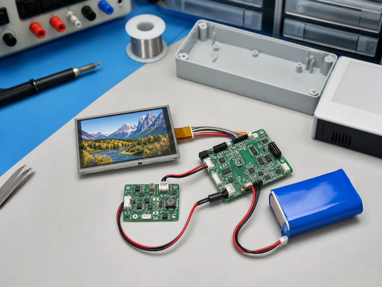 Backlight power is often separate from LCD logic power and should be reviewed during system design.
The mainboard should provide the correct LED current and dimming control. Driving the backlight directly from an unstable voltage source can create brightness variation, overheating, shortened lifetime, or LED damage.
For battery-powered products, backlight current can dominate total power consumption. Define brightness target, dimming method, duty cycle, and thermal condition before finalizing the power design.
6. Touch Panels Add More Electrical Requirements
If the LCD module includes capacitive touch, the touch controller may have its own supply voltage, reset pin, interrupt pin, I2C voltage, firmware settings, and ESD protection needs.
Review capacitive touch TFT LCD modules as a complete display-touch system. Confirm whether the touch FPC is separate from the display FPC, whether the touch controller voltage matches the mainboard, and whether level shifting is required.
Touch problems are often blamed on software, but voltage mismatch, weak pull-up design, grounding, or reset timing can also cause unstable behavior.
7. Consider Temperature and Voltage Margin
Voltage margin can change with temperature, battery level, cable length, and regulator tolerance. A design that works at room temperature may fail in a cold warehouse, hot enclosure, or low-battery condition.
If your product operates in harsh environments, compare the requirements with wide temperature TFT LCD modules. Test the display at the target temperature range and measure both logic and backlight behavior.
For long-lifecycle products, record the approved voltage conditions, test method, firmware version, and display lot information. This makes future supplier changes and quality analysis easier.
Practical Voltage Compatibility Checklist
Before approving a TFT LCD module, review these points:
- What is the LCD panel supply voltage?
- What is the logic interface voltage?
- Are reset, standby, chip select, clock, and data pins voltage-compatible?
- Does the processor need level shifting?
- What is the backlight LED current and voltage requirement?
- Is a constant-current LED driver required?
- What is the correct power-on and reset sequence?
- Does the touch controller need a separate supply?
- Are I2C pull-up voltages correct for touch?
- Has the final mainboard been tested across temperature and battery range?
How Sunshine Display Can Help
Sunshine Display supplies small color LCD display modules under 32 inches for global B2B customers. For OEM projects, Sunshine Display can help review display size, interface, logic voltage, backlight current, FPC, connector, touch panel, cover glass, operating temperature, and sample validation requirements.
If your project needs a stable LCD module for a compact device, share your processor platform, interface, supply voltage, backlight design, touch requirement, mechanical drawing, and expected volume. You can contact Sunshine Display to discuss suitable LCD module options before PCB layout or sample approval.
FAQ
Can a 3.3 V MCU drive every TFT LCD module?
No. Some TFT LCD modules require 1.8 V logic or specific signal levels, so the MCU and display voltage must be checked before connection.
Is LCD logic power the same as backlight power?
Usually no. LCD logic power and LED backlight power often have different voltage and current requirements.
When do I need a level shifter?
You may need a level shifter when the processor signal voltage does not match the LCD module input voltage or touch controller voltage.
Can wrong voltage damage an LCD module?
Yes. Over-voltage on power or signal pins can damage the display driver IC, touch controller, or backlight circuit.
Can Sunshine Display help check voltage compatibility?
Yes. Sunshine Display can help review logic voltage, backlight current, connector pinout, touch voltage, and sample validation requirements for small TFT LCD modules.