How LCD Module Tolerances Affect OEM Assembly
LCD display module selection is often discussed through size, resolution, brightness, interface, and touch function. Those specifications matter, but another factor can decide whether the final product assembles smoothly: tolerance control. A display that works perfectly on the bench can still create problems if the enclosure opening, cover lens, gasket, FPC exit, or screw boss position does not match the real tolerance stack.
For OEM teams sourcing LCD display modules up to 32 inches, tolerance review should start before tooling. Small and medium-size LCD modules may have tight space around the connector and cover lens. Larger industrial/color TFT LCD modules may need more attention to flatness, support points, frame strength, and transportation handling. In both cases, the goal is the same: make the final assembled product stable, readable, and repeatable in production.
LCD module tolerance review should include the enclosure opening, viewing area, active area, thickness stack, and cable clearance.
Why Tolerances Matter in Display Integration
Every physical part has dimensional variation. The LCD outline, metal frame, touch panel, cover glass, gasket, plastic enclosure, adhesive tape, and mounting bracket all have tolerances. When these tolerances stack in the same direction, the final assembly can become too tight, too loose, or visually misaligned.
A small mismatch may cause the viewing area to be partially covered. A tighter stack may press the bezel or gasket against the LCD surface. A loose stack may let the display move inside the enclosure during vibration or shipping. These are not only cosmetic issues. They can create light leakage, touch instability, pressure marks, poor sealing, assembly scratches, or field failures.
When reviewing Sunshine Display's LCD display module product range, buyers should compare not only headline specifications, but also outline drawings, active area, viewing area, thickness, connector position, and mechanical notes.
Active Area, Viewing Area, and Enclosure Opening
The active area is the pixel area that displays the image. The viewing area is the visible window defined by the module or cover design. The enclosure opening is the hole or transparent area in the customer's product. These three areas should not be treated as the same dimension.
If the enclosure opening is too small, it may hide content at the edge of the display. If it is too large, the customer may see the LCD border, adhesive, gasket, or internal structure. For products with a cover lens, printing and mask design should also be reviewed so the visible window looks centered after assembly.
Engineers should check the worst-case tolerance condition, not only nominal dimensions. A nominally centered display can shift after plastic molding tolerance, gasket compression, screw tightening, and adhesive placement are all included.
Thickness Stack and Compression Margin
Thickness is another common risk. The stack may include cover glass, adhesive or air gap, touch panel, LCD module, foam gasket, bracket, and enclosure support. If the stack is too tall, the enclosure may force pressure onto the display. If it is too short, the module may not be held firmly.
Projected capacitive touch designs need special attention because cover glass thickness, air gap, bonding method, and grounding can affect touch performance. Sunshine Display's capacitive touch TFT LCD modules can support many OEM product designs, but the final enclosure stack should still be validated with real samples.
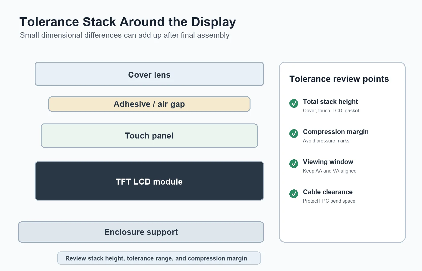 Cover lens, adhesive, touch panel, LCD module, gasket, and enclosure support should be reviewed as one stack.
Mounting Features and Support Points
Screw bosses, plastic clips, metal brackets, and adhesive tape should support the display through suitable areas. Hard features should not push directly behind the active display area. Uneven support can bend the module or create local pressure marks that appear only after the unit is fully assembled.
For standard indoor products, many teams start with standard TFT LCD modules and then design the enclosure around the selected outline. For equipment that needs wider viewing angle or better color stability from different positions, IPS TFT LCD modules may be more suitable, but the same mechanical tolerance checks still apply.
The fixing method should match the product environment. A desktop device, handheld controller, wall-mounted panel, vehicle display, and industrial machine interface may need different support structures. Larger displays generally require better control of flatness and bracket strength.
FPC Exit and Connector Clearance
Even when the LCD fits the enclosure, the FPC and connector can create assembly problems. The cable needs enough space to bend without being pinched. The connector needs access for assembly and inspection. If the cable route is too tight, operators may damage the FPC, create intermittent connection failures, or make the product difficult to service.
The FPC exit direction should be checked in the real mechanical design. A drawing may show the connector position clearly, but the final product may also include ribs, battery packs, PCB components, speakers, or sealing structures that reduce available space.
Temperature and Material Expansion
Plastic, metal, glass, adhesive, and LCD materials expand differently with temperature. This is especially relevant for outdoor equipment, vehicles, cold storage devices, and industrial systems. A design that fits at room temperature may become tight at high temperature or loose at low temperature.
If the application needs a broad temperature range, review both the display specification and the enclosure material. Sunshine Display's wide temperature TFT LCD modules are useful for demanding environments, but thermal expansion and gasket behavior still need product-level validation.
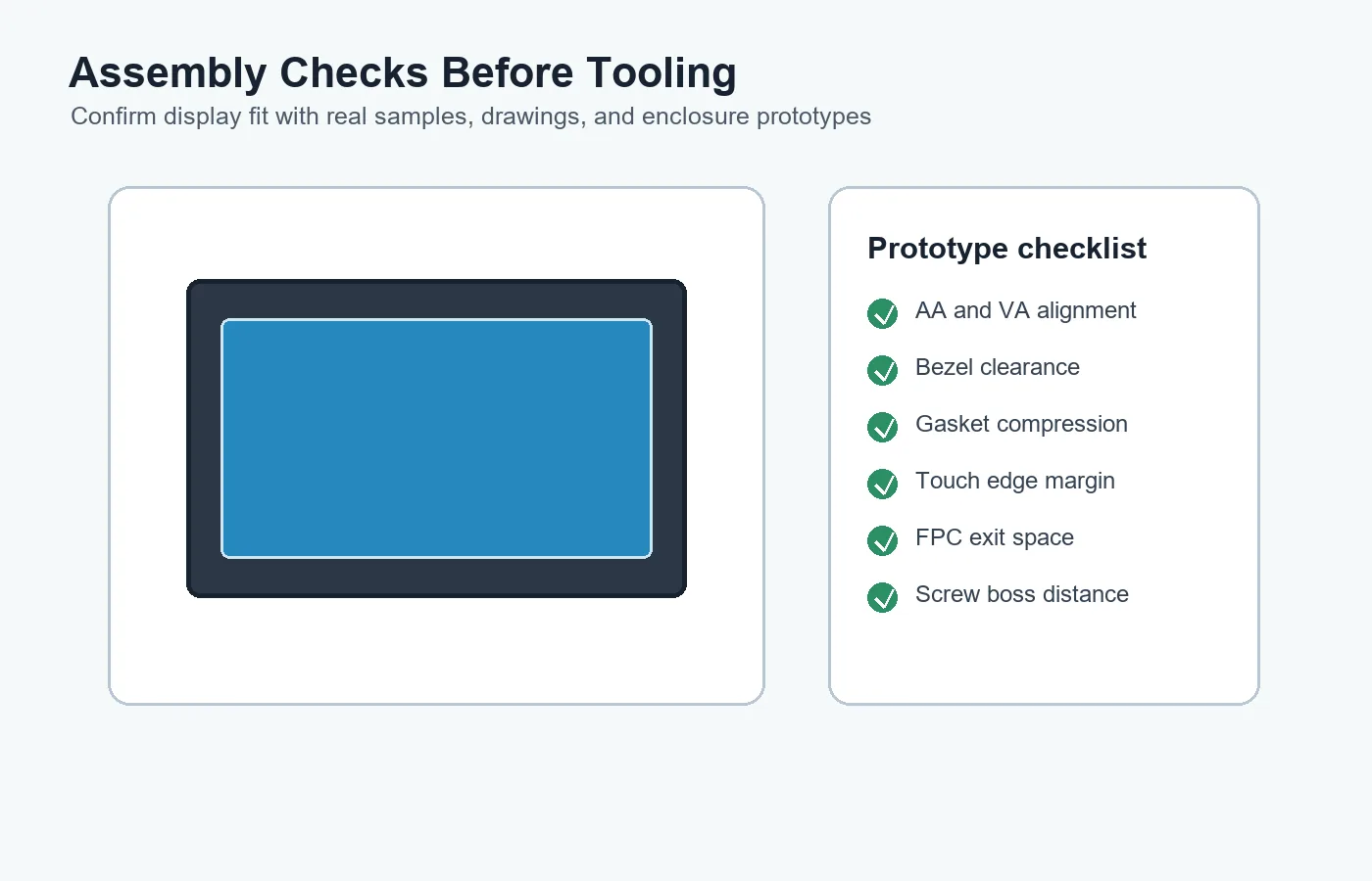 Prototype checks should confirm active area alignment, bezel clearance, gasket compression, touch margin, FPC space, and screw boss distance.
Practical Checks Before Tooling
Before opening enclosure tooling, ask for 2D drawings and, when available, 3D model data. Check the LCD outline, active area, viewing area, total thickness, connector position, FPC bending space, touch stack, and cover glass overlap. Then review these dimensions against the enclosure model.
During prototype assembly, inspect the display after the product is fully built. Check white, black, gray, and color screens. Look for edge shadows, pressure marks, uneven brightness, touch drift, glass stress, and cable interference. Also confirm that production operators can assemble the module consistently without special handling tricks.
Buying Advice for OEM Projects
When sourcing an LCD display module, send the supplier the real application, enclosure concept, target size, interface, brightness, touch requirement, operating temperature, and any special mechanical limits. This helps the supplier identify tolerance risks early instead of after tooling is complete.
Sunshine Display supports small, medium-size, and larger industrial/color LCD display modules up to 32 inches for OEM applications. If your project is moving from display selection to enclosure design, you can contact Sunshine Display to review module drawings, tolerance risks, and integration options before mass production.
FAQ
What LCD dimensions matter most for enclosure design?
The outline size, active area, viewing area, total thickness, connector position, FPC exit direction, and tolerance notes are the most important dimensions for enclosure design.
Why should active area and viewing area be checked separately?
The active area is the pixel area, while the viewing area is the visible window. The enclosure opening and cover lens mask should be designed around the viewing requirement, not only the active pixel size.
Can gasket pressure damage an LCD module?
Yes. Excessive or uneven gasket pressure can create pressure marks, touch issues, light leakage, or glass stress. Compression should be validated with the complete mechanical stack.
Should tolerances be reviewed before or after tooling?
They should be reviewed before tooling. After tooling is complete, fixing tolerance problems can require expensive enclosure changes.
Do larger LCD modules need different tolerance checks?
Larger modules often need more attention to flatness, bracket support, frame strength, and shipping protection, while smaller modules often need tighter review of connector clearance and compact cable routing.