LCD Module ESD Protection Guide for OEM Products
ESD protection should be reviewed from handling and assembly through final product testing.
Electrostatic discharge, usually called ESD, is a practical reliability issue in LCD display module projects. A TFT LCD module may work correctly during sample testing, but still fail in the final product if the touch panel, FPC, connector, grounding, enclosure, or handling process is not designed correctly.
For color LCD display modules under 15.6 inches, ESD protection matters in industrial controllers, medical instruments, handheld devices, smart home panels, POS terminals, meters, EV chargers, and public operation panels. These products are touched frequently and may be used in dry environments where static discharge is more likely.
This guide explains what OEM buyers and engineers should check when selecting and validating TFT LCD modules for ESD-sensitive applications.
1. Why ESD Matters for LCD Modules
An LCD module includes glass, polarizer, backlight, driver IC, FPC, connector, touch panel, and sometimes cover glass or optical bonding. ESD can enter the system through user touch, exposed metal parts, connector pins, FPC handling, or assembly equipment.
The result may be immediate failure, display flicker, touch malfunction, reset behavior, image noise, or latent damage that appears later. For OEM products, latent damage is especially risky because it may pass factory inspection but create field failures.
ESD protection should therefore be considered during design review, sample evaluation, pilot production, and incoming quality inspection.
2. Understand the ESD Path
The key question is where the discharge energy goes. In a touch display product, ESD may enter through cover glass edges, capacitive touch sensor, metal frame, FPC, connector, or enclosure. The system should provide a controlled path to ground rather than allowing discharge through sensitive ICs.
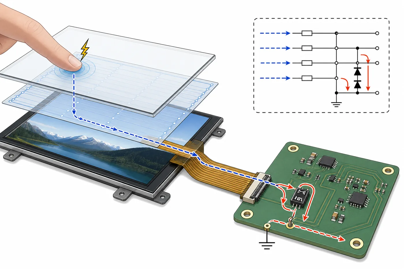 Touch panel, FPC, connector, PCB grounding, and ESD components should work as one protection system.
For capacitive touch modules, review the touch sensor design, cover lens structure, controller IC, FPC layout, shielding layer, and ground connection. For display signals, review whether the connector and PCB provide proper ESD components and return paths.
The LCD supplier and mainboard engineer should review the full path together. A display module cannot guarantee system-level ESD performance if the enclosure and mainboard grounding are weak.
3. Protect the FPC and Connector
The FPC and connector are common weak points. Operators may touch exposed contacts during assembly. A connector may also become an entry point if the product is serviced or assembled in a non-ideal environment.
Good practice includes ESD-safe packaging, anti-static trays, protective film, ESD-safe workstations, wrist straps, and controlled handling instructions. On the PCB side, ESD protection components should be placed close to the connector when needed.
If the FPC includes touch signals, I2C lines, reset pins, interrupt pins, or high-speed display lines, the protection strategy should be reviewed carefully. Adding the wrong component can affect signal quality, so protection and signal integrity must be balanced.
4. Review Touch Panel and Cover Glass Design
Touch displays need special attention because the user directly interacts with the front surface. Capacitive touch performance can be affected by grounding, metal frames, cover glass thickness, air gaps, electrical noise, and ESD discharge.
If the product uses custom cover glass, review edge design, printing, optical bonding, touch sensor size, and grounding. ESD may occur near the edge of the cover glass or around openings, especially in public or industrial products.
For products with metal enclosures, define whether the metal frame is grounded, floating, or isolated. A poorly controlled metal frame can create inconsistent ESD behavior.
5. Test With the Real Product Structure
ESD testing should not rely only on an open LCD sample. The final product structure changes the result. Enclosure material, screw connection, grounding wire, cover glass, PCB layout, cable routing, and power adapter all influence ESD performance.
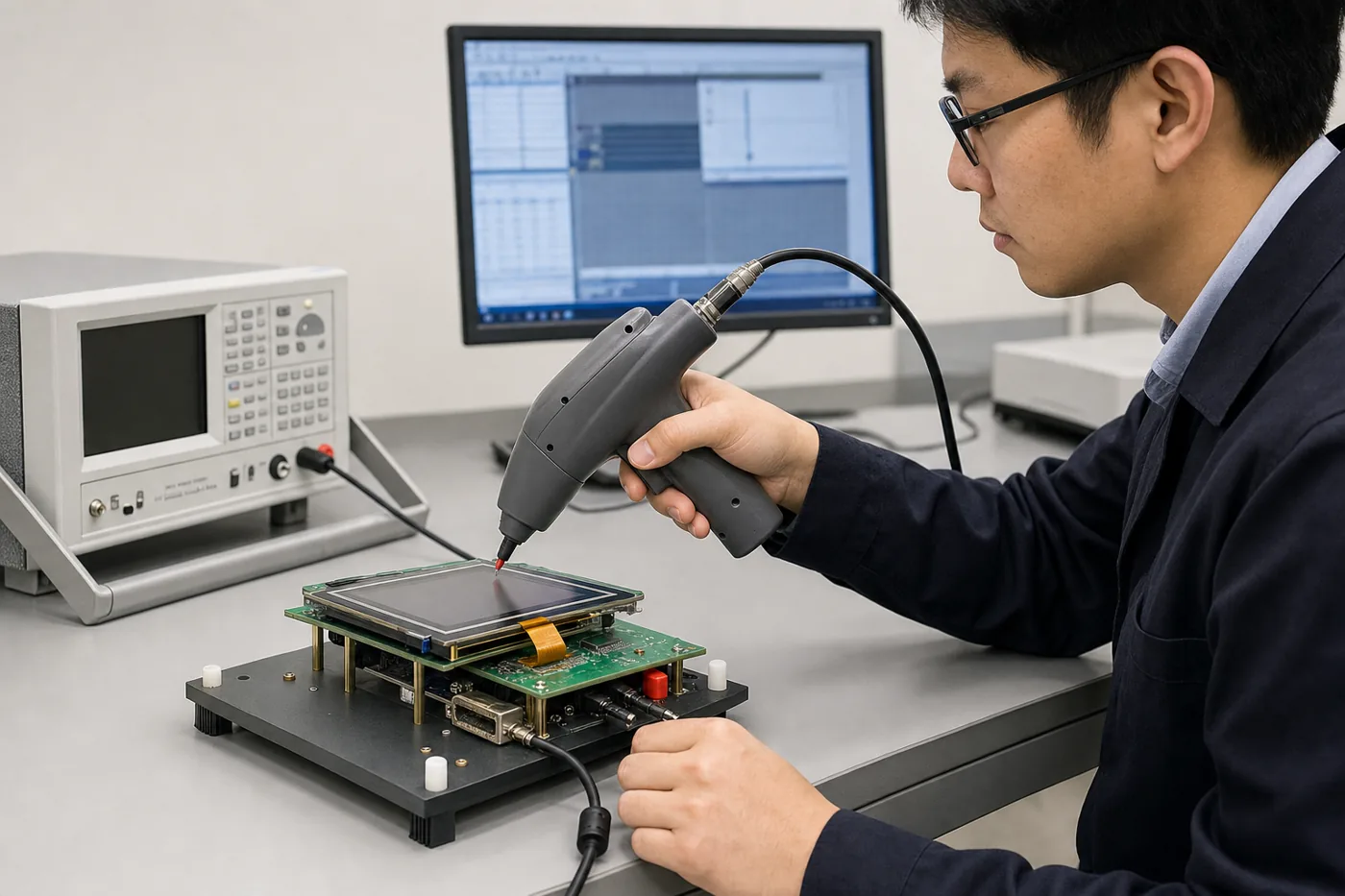 ESD testing should use the real product structure, not only an open display sample.
During validation, test normal display operation, touch response, sleep/wake behavior, backlight control, and communication stability after discharge events. Record whether the product recovers automatically or requires power cycling.
If your product must meet a specific IEC 61000-4-2 test level or customer requirement, confirm the test condition early with the supplier and system engineer.
6. Consider Enclosure Grounding and System Design
A strong LCD module cannot compensate for poor system grounding. The enclosure, PCB ground, touch panel ground, metal frame, shield layer, and power supply should be reviewed as one system.
 Enclosure grounding and touch panel design can strongly influence final ESD performance.
Plastic enclosures may require different protection strategy from metal enclosures. For metal housings, grounding points and conductive paths should be intentional. For plastic housings, ESD may still enter through touch surface, connectors, screws, or nearby metal parts.
If wireless modules, motors, relays, or high-current circuits are close to the display, consider both ESD and EMI during layout review.
7. Practical Buying Checklist
Before approving an LCD module for production, review these points:
- What ESD level does the final product need?
- Is the requirement for contact discharge, air discharge, or both?
- Does the module include capacitive touch or resistive touch?
- Is the touch controller protected properly?
- Are FPC contacts protected during handling?
- Are connector-side ESD components required on the mainboard?
- Is the metal frame grounded, floating, or isolated?
- Has ESD been tested inside the final enclosure?
- Does the product recover automatically after discharge?
- Are packaging and handling instructions ESD-safe?
How Sunshine Display Can Support ESD Review
Sunshine Display supplies LCD display and Touch Screen under 32 inches for global B2B customers. For OEM projects, Sunshine Display can help review display size, interface, touch panel, cover lens, FPC, connector, optical bonding, grounding considerations, and sample validation needs.
If your product has ESD, EMI, or harsh-environment requirements, share the application, enclosure structure, touch type, mainboard interface, expected test level, and production volume. Sunshine Display can help recommend a practical LCD module structure and support sample review.
Contact Sunshine Display to discuss your LCD module ESD protection requirements before sample approval or mass production.
FAQ
Can ESD damage an LCD module?
Yes. ESD can damage driver ICs, touch controllers, FPC contacts, or system circuits, and may also cause display reset, flicker, or touch malfunction.
Is ESD protection only the LCD supplier's responsibility?
No. ESD performance depends on the LCD module, touch panel, FPC, connector, PCB layout, grounding, enclosure, and handling process.
Should ESD testing be done on the final product?
Yes. Final product structure can strongly affect ESD behavior, so testing should be done with the actual enclosure and mainboard.
Do capacitive touch LCD modules need special ESD review?
Yes. Touch panels are direct user-contact surfaces, so cover glass, sensor design, grounding, and controller protection should be reviewed carefully.
Can Sunshine Display support ESD-sensitive LCD projects?
Yes. Sunshine Display can help review small TFT LCD module structure, touch design, FPC, connector, and sample validation requirements for ESD-sensitive applications.