Welding equipment displays must remain readable and reliable around electrical noise, metal dust, gloves, and demanding production workflows.
Modern welding systems use graphical displays to manage process selection, current, voltage, wire feed, pulse settings, job memory, alarms, and service diagnostics. The screen must communicate these values quickly while operators wear protective equipment and work in a bright, electrically noisy fabrication environment.
Choosing an LCD module for industrial welding equipment therefore involves more than matching diagonal size and resolution. The complete display system must suit the controller, front panel, user workflow, electromagnetic environment, thermal design, and product lifecycle. Sunshine Display supports industrial display modules for OEM equipment, including TFT LCD modules up to 32 inches and customized display assemblies.
Start With the Welding Workflow
Different welding systems place different demands on the interface. A compact manual power source may use a small screen with two rotary encoders. A robotic welding cell may need a larger panel for recipes, production data, fault history, and maintenance access. Multiprocess equipment can require clear navigation among MIG, TIG, pulse, synergic, and setup modes.
List the tasks that operators perform most frequently. Primary parameters should be readable at a glance, while secondary settings should remain easy to reach without crowding the screen. Large touch targets, clear status colors, and logical grouping matter when users wear gloves or look through protective eyewear. Test the real UI on the selected module instead of relying on a colorful demonstration image.
Match Size and Resolution to Viewing Distance
Screen size should follow the enclosure and normal operator position. A compact module can work on portable welding equipment, while medium and larger displays may suit automated cells and production stations. Resolution should support the required graphics and text without forcing the processor to handle unnecessary pixel bandwidth.
Mechanical review must include the active area, module outline, FPC exit, connector position, mounting points, bezel opening, cover lens, gasket, and cable clearance. If operators approach from different angles, an IPS TFT LCD module can provide more stable contrast and color than a narrow-viewing-angle panel.
Design for Workshop Readability
Fabrication shops combine overhead lighting, reflections from metal surfaces, shadows, and occasional high-intensity welding light. Brightness is important, but evaluate it with contrast, viewing angle, front-window reflection, and surface treatment. Excessive brightness can add heat and shorten backlight life without solving glare from the cover lens.
Use realistic screens during evaluation: small parameter values, warning colors, disabled controls, trend lines, and alarm messages. Check the screen from standing and seated positions. If the machine operates near open doors or semi-outdoor areas, test stronger ambient light and consider anti-glare treatment or optical bonding.
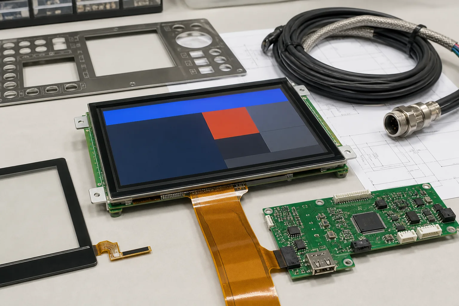 The LCD, touch layer, controller, cable, front panel, and enclosure should be reviewed as one industrial display system.
Control Electrical Noise at System Level
Welding equipment can generate substantial conducted and radiated interference through high-current switching, long cables, motors, contactors, and grounding paths. A display that works on a development bench may show flicker, touch errors, communication loss, or resets after installation in the final machine.
Interface selection should begin with the main controller. RGB, LVDS, MIPI, or another link may be suitable depending on size, resolution, processor capability, and cable length. Keep high-current paths separated from display signals, use controlled grounding, and review shielding and connector retention. The backlight driver and touch controller also need stable power and filtering.
EMC testing should run actual welding cycles while the UI changes pages, stores settings, and communicates with the controller. Recovery behavior matters as much as immunity: if interference disrupts a link, the display system should return to a known state without presenting misleading parameters.
Select Touch and Physical Controls Together
Touch can simplify complex menus and job selection, but welding environments require practical validation. Gloves, dust, metal particles, moisture, and electrical noise can affect operation. A capacitive touch TFT LCD module may support glove operation when the controller and cover lens are correctly tuned, but testing with the intended gloves is essential.
Critical adjustments may still benefit from physical knobs or keys. A hybrid interface allows fast parameter changes without precise touch input. The UI should prevent accidental activation and provide clear confirmation for saved programs or high-impact settings. Finalize front-panel grounding and cover-lens thickness before touch tuning.
Account for Heat, Dust, and Mechanical Stress
Welding power electronics generate heat, and cooling airflow may carry metal dust into the enclosure. Position the display away from hot components and evaluate it at the expected internal cabinet temperature. For demanding installations, wide-temperature TFT LCD modules can be reviewed with the thermal and backlight requirements.
The front assembly should protect the module from impact, dust, and cleaning procedures. Gasket compression must seal the opening without uneven pressure on the LCD. Excessive mounting stress can cause light leakage, mura, or touch instability. Include vibration, transport shock, connector retention, and cable bend radius in mechanical validation.
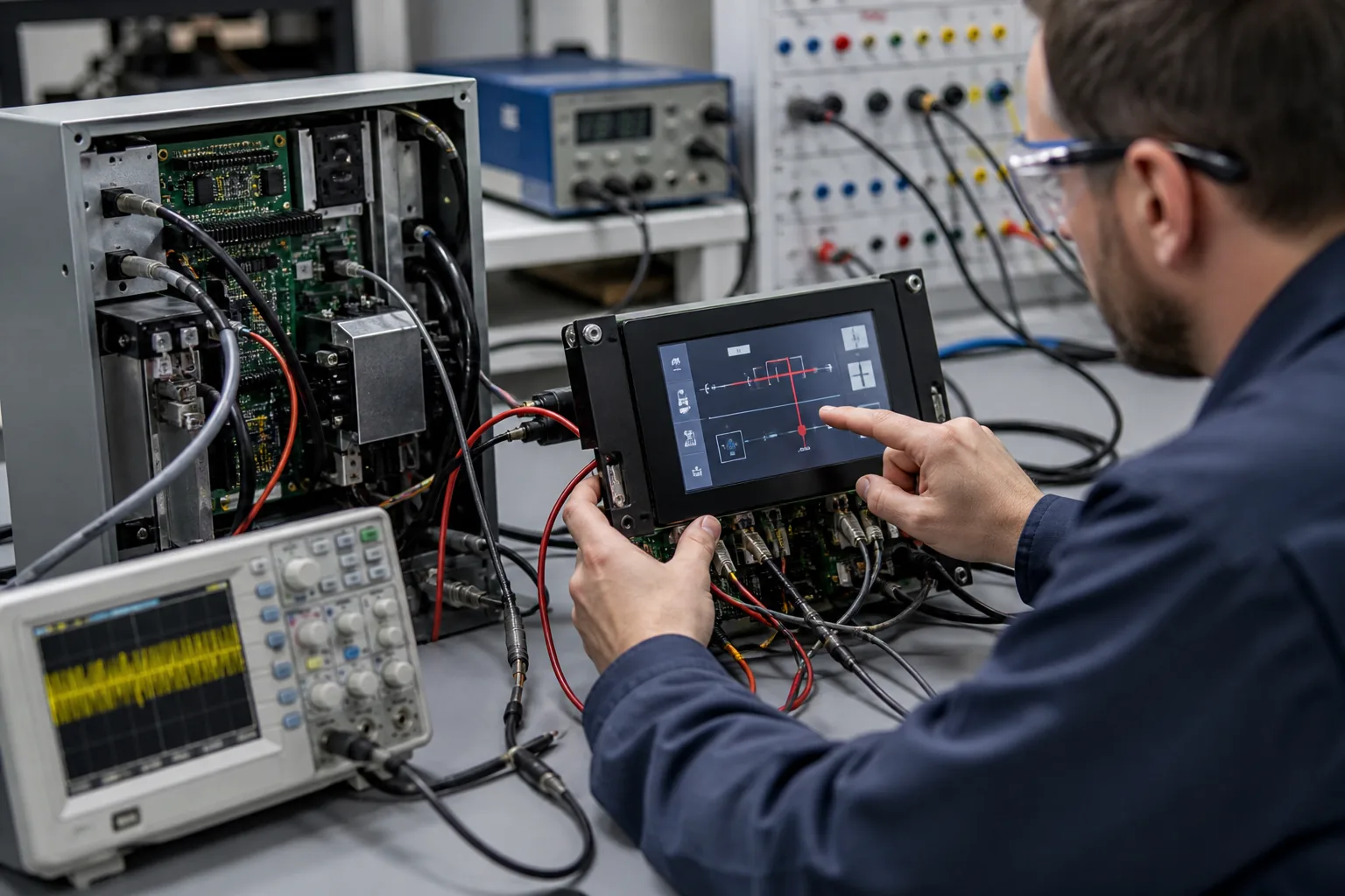 System-level validation should reproduce welding noise, cable routing, grounding, touch operation, and thermal conditions before production release.
Validate With the Final Machine
Begin with display samples connected to the production controller. Confirm startup timing, image stability, color depth, backlight control, touch response, sleep behavior, and firmware recovery. Then install the assembly in the final front panel and repeat tests with normal welding cables, grounding, cooling fans, and power stages operating.
Run thermal tests at high workload, touch tests with gloves, viewing tests under workshop lighting, and EMC tests across representative welding modes. Review whether alarm information remains visible during faults and whether the interface returns safely after a power interruption. Production inspection should include appearance, touch function, backlight uniformity, connector seating, and critical UI pages.
Buying Questions for OEM Teams
An effective RFQ should include screen size, resolution, interface, brightness, viewing direction, touch requirement, cover-lens drawing, operating temperature, controller platform, expected cable length, annual volume, and product lifetime. Share the enclosure drawing and representative UI screens whenever possible.
Ask about module availability, backlight lifetime, change notification, compatible alternatives, touch firmware ownership, and customization limits. Custom options may include cover glass, printing, FPC, connector, backlight, touch tuning, controller board, and complete display subassembly. Early review helps control tooling cost and avoids redesign after compliance testing.
Sunshine Display can help OEM teams compare suitable TFT LCD technologies and assess mechanical, optical, touch, and lifecycle requirements. Contact Sunshine Display to discuss a display module or customized assembly for industrial welding equipment.
FAQ
What LCD technology works well in industrial welding equipment?
A TFT LCD with stable industrial availability is suitable for most graphical welding interfaces. IPS is useful when operators need consistent contrast and color from wider viewing positions.
Can capacitive touch work when operators wear welding gloves?
It can, but the touch controller, cover lens, glove thickness, grounding, and UI button size must be tested together. Some applications retain physical knobs or keys for critical adjustments.
Why is EMC testing important for a welding machine display?
Welding current switching and nearby motors can create conducted and radiated interference. Testing helps confirm that the image, touch controller, communication link, and firmware remain stable during real operation.