Industrial cleaning HMIs must keep cycle, temperature, tank, alarm, and maintenance information clear around stainless equipment and wet processes.
Industrial ultrasonic cleaning systems are used for precision components, automotive parts, medical instruments, electronics, optics, and metal assemblies. Their operator interfaces may control multiple tanks, ultrasonic power, frequency modes, temperature, filtration, rinsing, drying, timing, recipes, alarms, and maintenance schedules.
Selecting an LCD module for industrial ultrasonic cleaning equipment requires more than choosing a convenient screen size. The display assembly must remain readable and responsive around stainless surfaces, moisture, gloves, chemical residue, heat, vibration, and electrically switched loads. Sunshine Display supplies industrial display modules for OEM equipment, including TFT LCD modules up to 32 inches and customized touch assemblies.
Begin With the Cleaning Process
A compact single-tank cleaner may need only temperature, time, ultrasonic power, and start-stop status. A multi-stage production line can include washing, rinsing, passivation, drying, filtration, lifting mechanisms, and recipe management. Maintenance users may also need transducer diagnostics, heater status, pump alarms, fluid-life records, and service counters.
Map the user roles and normal operating sequence before selecting the display. Primary cycle information should remain visible at a glance. Recipe changes and service functions can sit on secondary pages with access control. Large touch targets and clear alarm hierarchy help operators work efficiently while wearing gloves.
Match Size and Resolution to the HMI
Screen size should follow the amount of information, viewing distance, available panel space, and controller capability. Small modules can suit benchtop equipment, while medium or larger displays can present multiple tanks, recipe steps, trend data, and diagnostics without crowded navigation.
Resolution should support the actual UI rather than an arbitrary specification target. Test small values, temperature trends, tank graphics, warning colors, and disabled controls. Mechanical review should cover the active area, module outline, thickness, mounting points, cable exit, connector clearance, bezel opening, gasket, and service access.
Operators may approach a cleaning line from different positions. An IPS TFT LCD module can provide more stable contrast and color from wider viewing angles, but brightness, interface, temperature, and lifecycle must still match the project.
Manage Reflections and Moisture
Stainless equipment and bright production lighting can create strong reflections around the HMI. Evaluate brightness together with contrast, viewing angle, cover-glass reflection, and surface treatment. Excessive backlight power can add heat and reduce lifetime without solving glare.
Moisture introduces another challenge. Droplets on the front panel can trigger false touches or make the screen harder to read. The enclosure, gasket, bonding method, cover glass, and touch firmware should be designed as one system. A sloped or shielded console can reduce direct liquid exposure while improving cleaning and drainage.
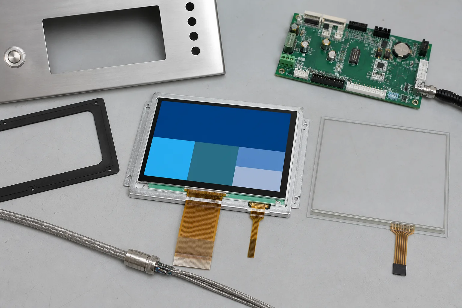 The module, touch panel, gasket, controller, cable, and stainless front panel should be reviewed together before enclosure release.
Choose Touch for Real Operating Conditions
A capacitive touch TFT LCD module can provide a clean interface for recipes and multi-stage controls. However, glove thickness, water droplets, cleaning solution, front-panel grounding, cover-lens thickness, and electrical noise all affect touch performance.
Test the intended gloves and realistic contamination. Large buttons, adequate spacing, and clear pressed states reduce operating errors. Critical functions may still use physical keys, selectors, or an emergency stop according to the machine safety design. Finalize the cover lens and enclosure stack before touch sensitivity is tuned.
The front material must also tolerate the cleaning chemicals used on the machine. Confirm compatibility of glass printing, adhesive, gasket, and surface coating with the actual maintenance procedure.
Control Heat and Electrical Interference
Heaters, ultrasonic generators, pumps, valves, motors, relays, and switching power supplies can affect the display environment. Keep high-current cables separated from display and touch signals. Review shielding, grounding, connector retention, and power filtering at the system level.
Interface choice depends on resolution, processor, refresh rate, and cable length. RGB, LVDS, MIPI, or another interface may be appropriate. Long links inside a multi-tank machine require particular attention to signal integrity and grounding. The display should start reliably and recover to a known state after power interruption or communication loss.
Internal temperature can rise during heated cycles. Evaluate the module and backlight at the expected enclosure temperature. For demanding ranges, review wide-temperature TFT LCD modules and verify optical performance, touch response, and backlight lifetime across the target conditions.
Protect the Display Mechanically
The front assembly should resist vibration, transport shock, moisture, repeated cleaning, and accidental impact. Gasket compression must provide sealing without placing uneven stress on the LCD. Excessive pressure can cause light leakage, mura, or touch instability.
Cable routing should avoid sharp bends, moving lifts, tank heat, and service pinch points. Connectors need retention and sufficient access for replacement. If the console is mounted above a wet process, consider drip paths and condensation so liquid cannot collect behind the cover lens or around cable entries.
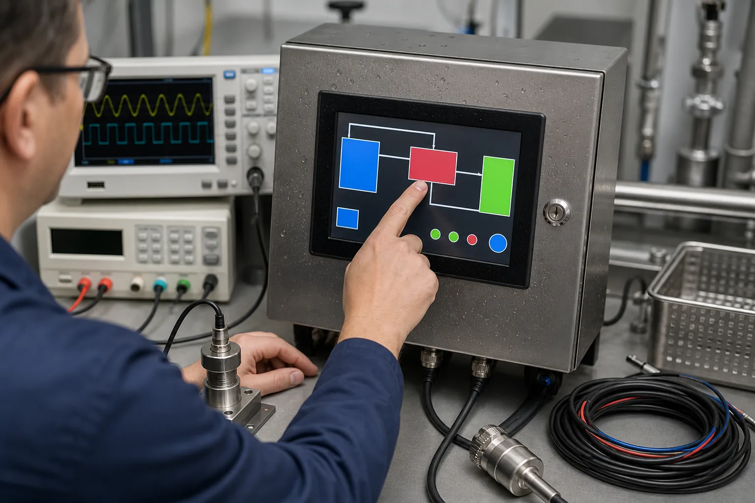 Validation should reproduce moisture, glove use, temperature, electrical noise, cable routing, cleaning procedures, and controller operation.
Validate the Complete Machine
Start with samples connected to the production controller. Confirm timing, image stability, color depth, brightness control, touch response, sleep behavior, and firmware recovery. Then install the display in the final enclosure with production cables, grounding, power supplies, pumps, heaters, and ultrasonic generators.
Run representative cleaning cycles while navigating the UI. Test gloves, droplets, cleaning chemicals, thermal limits, vibration, and factory lighting. Watch for false touch, flicker, communication errors, delayed updates, or resets. Verify that alarms remain visible and that interruption recovery never presents an unsafe or misleading machine state.
Practical RFQ Information
Provide the display supplier with target size, resolution, interface, brightness, viewing direction, touch requirement, cover-lens drawing, sealing target, operating temperature, controller platform, cable length, annual volume, and expected production lifetime. Representative screens and enclosure drawings make recommendations more accurate.
Ask about module availability, backlight lifetime, change notification, compatible alternatives, touch firmware ownership, and customization options. Custom work may include cover glass, printing, bonding, FPC, connector, backlight, touch tuning, controller board, and a complete display subassembly.
Sunshine Display can help OEM teams review optical, mechanical, touch, interface, environmental, and lifecycle requirements. Contact Sunshine Display to discuss an LCD module or customized display assembly for industrial ultrasonic cleaning equipment.
FAQ
What display is suitable for industrial ultrasonic cleaning equipment?
A stable industrial TFT LCD module is suitable for cycle selection, timing, temperature, alarms, and maintenance pages. IPS is useful when operators view the panel from different positions.
Can capacitive touch be used near water and cleaning solution?
Yes, but the touch controller, cover glass, sealing, grounding, gloves, droplets, and cleaning chemicals must be tested together in the final enclosure.
Why test the LCD in the complete cleaning machine?
The final machine introduces heat, moisture, vibration, switching loads, grounding paths, and cable routing that are not present in a simple display bench test.