LCD Module Mounting Design Guide
Selecting the right LCD display module is only half of a successful OEM project. The other half is mounting it correctly inside the product. A good mechanical design protects the LCD glass, controls pressure around the active area, keeps the FPC and connectors safe, and makes the final device easier to assemble and service.
For buyers and engineers sourcing LCD display modules up to 32 inches, mounting design should be reviewed early, before enclosure tooling is finalized. A 3.5 inch handheld controller, a 7 inch panel PC, a 15.6 inch industrial HMI, and a larger commercial display may all use different fixing methods, but the same core questions apply: where does the load go, how is the display protected, and can the screen remain readable after final assembly?
Mounting design should review the LCD module, gasket, cover glass, bracket, and enclosure together.
1. Start With the Mechanical Stack
The mechanical stack usually includes the LCD module, backlight frame, touch panel if required, cover glass or cover lens, gasket, front bezel, rear bracket, screws or bosses, and the product enclosure. These parts should be considered together instead of being designed one by one.
If the enclosure opening is too small, it may cover the active area or create shadows near the edge of the display. If the opening is too large, the product may look unfinished and leave the LCD edge exposed. If the gasket is too thick or too hard, it can add pressure that affects touch performance or creates visible stress on the LCD.
When reviewing standard modules from Sunshine Display's LCD display module product range, check the outline drawing, active area, viewing area, thickness, connector position, and recommended mounting notes. These dimensions should be transferred into the mechanical model before prototype tooling.
2. Choose the Right Mounting Method
Common mounting methods include screw fixing, bracket fixing, front bezel clamping, adhesive tape, and full enclosure support. The best choice depends on product size, vibration level, service requirements, IP rating, appearance, and cost.
Screw or bracket fixing gives a controlled load path and is often used for industrial products. The screw force should go through the metal frame, bracket, or enclosure support rather than through the LCD glass. For larger modules, this method usually gives better stability during transportation and field use.
Front bezel and gasket mounting can create a clean appearance and help protect the display edge. It is common in control panels, access systems, and equipment interfaces. The gasket must be selected carefully so it seals and cushions without applying uneven pressure.
Adhesive tape is useful for slim products where visible screws are not acceptable. However, engineers should confirm adhesive strength, heat aging, rework process, and surface preparation. Tape-only designs can be convenient, but they need proper validation before mass production.
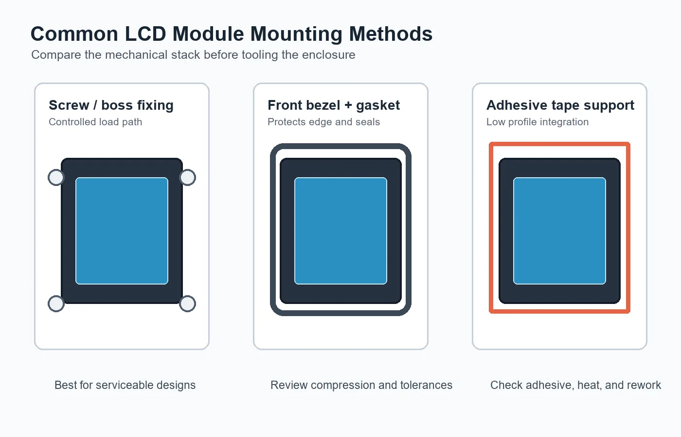 Different mounting methods suit different enclosure designs, vibration levels, and service needs.
3. Protect the LCD From Mechanical Stress
LCD modules are sensitive to bending, point pressure, and uneven compression. Mechanical stress can cause light leakage, mura, touch drift, abnormal display marks, or glass damage. These failures may not appear during a quick power-on test, so mechanical review is important during sample evaluation.
Avoid placing hard ribs, screw bosses, metal edges, or plastic clips directly behind the active area. If the enclosure needs internal support, keep it on the module frame or designed support area. For wide or thin modules, check whether the enclosure may twist during assembly or when the product is mounted on a wall or machine.
If the product uses a touch panel, especially projected capacitive touch, the cover lens and grounding structure should also be reviewed. Sunshine Display's capacitive touch TFT LCD modules can be supplied with touch solutions, but the final touch experience still depends on cover glass thickness, air gap or bonding design, enclosure grounding, and the user's operating environment.
4. Plan the Cover Glass and Bezel
Cover glass improves appearance and protects the display, but it changes the optical and mechanical design. The cover glass should overlap the display edge enough to hide tolerance variation, but not so much that it blocks the viewing area. If the cover lens is bonded, engineers should review the bonding area, adhesive selection, dust control, and edge sealing.
For outdoor, semi-outdoor, or high-ambient-light equipment, cover glass reflection can reduce readability. In these cases, the LCD module, brightness, optical bonding, and surface treatment should be selected as a system. Sunshine Display's standard TFT LCD modules are suitable for many indoor products, while applications needing wider viewing or better readability may also consider IPS TFT LCD modules.
The bezel should not press unevenly on the LCD or touch surface. A small amount of tolerance in the plastic part, gasket, or glass can create pressure points if the stack has no margin. During prototype review, inspect the screen at white, black, gray, and color patterns after the unit is fully assembled.
5. Keep Cable Routing Serviceable
Even when the article topic is mechanical mounting, cable routing cannot be ignored. The FPC, connector, and any interface cable need clearance and a controlled bend radius. They should not be pinched by the enclosure, pulled during assembly, or forced against sharp plastic edges.
For larger display modules, the cable may need strain relief or a fixed route to prevent movement during vibration. For compact products, the cable path may be short but crowded. In both cases, the assembly sequence should be tested by the operators who will build the product, not only by the engineer who designed it.
If the project needs a wide operating temperature range, the mechanical design should also account for thermal expansion, adhesive behavior, and gasket aging. For products exposed to cold storage, outdoor kiosks, vehicles, or industrial sites, review suitable wide temperature TFT LCD modules together with the enclosure material.
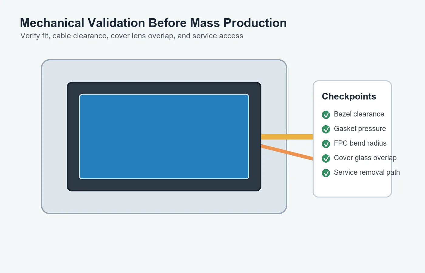 Final validation should check fit, cable clearance, gasket pressure, and cover lens overlap after assembly.
6. Validate Before Tooling and Mass Production
Before opening production tooling, build a checklist for mechanical validation. Confirm the LCD outline fits the enclosure, the active area is not blocked, the gasket compression is controlled, the FPC has clearance, the cover glass position is stable, and the module can be removed or replaced if service is required.
For sample testing, evaluate the display after full assembly, not only as a loose module on the bench. Check brightness uniformity, touch response, viewing angle, display noise, and edge appearance. Run basic vibration, drop, temperature, and aging tests according to the product's real application.
It is also useful to request updated drawings, 2D files, 3D models, and mounting recommendations from the display supplier. Early review reduces the risk of changing enclosure tooling after the display has already been selected.
Buying Advice for OEM Projects
When sourcing an LCD display module, ask the supplier for the outline drawing, recommended viewing area, connector location, thickness tolerance, touch panel stack, cover glass options, and any mechanical restrictions. If your product has vibration, outdoor use, public access, cleaning requirements, or long service life needs, mention these conditions at the beginning.
Sunshine Display supports small and medium-size LCD modules as well as larger industrial/color TFT LCD modules up to 32 inches. If your team is comparing module sizes, touch structures, or mounting approaches, you can contact Sunshine Display for a practical review before final enclosure design.
FAQ
What is the safest way to mount an LCD display module?
The safest method is to support the LCD through its frame, bracket, or designed mounting area while avoiding point pressure on the glass or active display area. The best structure depends on module size, enclosure type, vibration, and service requirements.
Can adhesive tape be used to mount a TFT LCD module?
Yes, adhesive tape can be used in slim or clean-front designs, but it should be validated for heat, aging, surface preparation, peel strength, and rework. Tape-only mounting is not ideal for every industrial or high-vibration product.
How much clearance should be kept around the active area?
Clearance depends on the module drawing, enclosure tolerance, cover glass overlap, and viewing area. Engineers should avoid covering the active area and should allow enough tolerance so the final assembled unit does not show edge shadows or pressure marks.
Does cover glass affect LCD module mounting?
Yes. Cover glass changes thickness, reflection, touch performance, sealing, and compression behavior. It should be reviewed together with the gasket, bezel, bonding method, and LCD module specification.
When should mounting design be discussed with the LCD supplier?
Mounting design should be discussed before enclosure tooling. Early review helps confirm the display outline, FPC direction, connector clearance, gasket pressure, touch stack, and possible custom options.