A replacement TFT module can fit the cutout and pass a basic power-on check, yet still make a machine look like it has two different interfaces when a second unit is installed. Differences in white point, gray steps, color balance, or brightness are easy to miss when samples are viewed on separate benches. They become obvious when operators compare adjacent machines or when a repair team replaces one panel months later.
Compare modules under the same image, settings, and viewing conditions.
Define what “matching” means for the product
Color consistency is not a single pass/fail property that can be judged from a supplier’s specification sheet alone. The acceptable appearance depends on the interface: a machine status panel may need recognizable alarm colors and legible gray controls, while an instrument that displays traces or visual measurements may rely on subtler distinctions. Start with the decisions a user makes from the screen, then identify the colors and brightness relationships that must remain clear.
Write those expectations into the sample approval record. Name the reference unit or approved sample, the test image, brightness setting, host board, viewing direction, ambient lighting, and any measurement method used. If a value must meet an agreed tolerance, record the instrument, measurement geometry, and the agreed limit with the display supplier. Avoid using “same color” as the complete requirement; it gives incoming inspection no repeatable way to decide whether a shipment is acceptable.
For a general industrial interface, the standard TFT LCD range provides a starting point for comparing module formats and display types. The selected panel still needs to be evaluated with the system electronics and the actual interface graphics.
Make the comparison repeatable
Put the candidate modules side by side and feed them the same static image from the same host, rather than comparing photos or screenshots taken at different times. Use identical brightness, contrast, gamma, and color-processing settings wherever those controls exist. Keep the modules at the same angle and distance, and remove glare or strongly colored light from the test area. If a panel needs a defined stabilization period before review, agree on that period and use it for every sample.
Include more than a bright, saturated test picture. A useful set covers white and near-white, black and near-black, several neutral gray steps, primary and secondary colors, and smooth gradients. Then show screens taken from the product itself: a dim alarm, a disabled control, a trend line, and the normal operating screen. The sample should be checked with the content and viewing distance expected in service, not just with a full-screen color patch.
 Use a controlled grayscale and color pattern before judging application screens.
Human review is useful for spotting distracting differences, but it is sensitive to viewing conditions and individual perception. If visual appearance is critical, use an appropriate calibrated instrument and document where and how readings are taken. Measurements should support the acceptance plan agreed with the supplier; a number without a defined method can create false confidence.
Separate panel variation from the host image path
When two modules look different, the LCD panel may not be the only cause. The host processor may apply different color conversion, gamma tables, bit depth, or image scaling. A board revision can also change display timing or backlight drive. Before rejecting a sample, send a known reference image through the same host and firmware to each module, then inspect the display settings and signal path for differences.
Record the module part number and revision, host-board revision, firmware build, display configuration, and brightness command used during the check. This gives engineering a way to reproduce a mismatch and helps sourcing distinguish a display change from a system change. Keep the approved sample and test files under revision control so later comparisons use the same basis.
For equipment viewed from several positions, assess the panel from the operator’s real eye line and from the angles at which service staff will inspect it. An IPS TFT module may be worth evaluating when a wider viewing angle is part of the use case, but viewing angle alone does not guarantee identical appearance across modules. Confirm performance with the intended graphics, brightness, and assembly.
Turn sample approval into incoming inspection
The approved sample should become the reference for production lots, not a one-time engineering artifact. Agree on an incoming sampling plan with the supplier and identify which checks apply to every unit and which apply to a representative sample. A practical visual screen can look for obvious color imbalance, uneven illumination, stuck or missing pixels, and inconsistent response to the chosen test patterns. Define how borderline observations are escalated and who makes the final decision.
Keep lighting and setup consistent between receiving inspections. A phone photograph is useful for documenting a defect, but its auto exposure and white balance make it a poor color comparator. If records must include images, lock the camera settings and include the reference screen in the frame; treat the image as supporting evidence rather than a measurement.
Ask the supplier to notify the project team before changes that could affect the approved appearance, including a panel revision, backlight, driver configuration, or source change. Re-run the comparison when a change is proposed. For equipment built over several years, retain the approved test image and acceptance notes alongside the bill of materials and revision history.
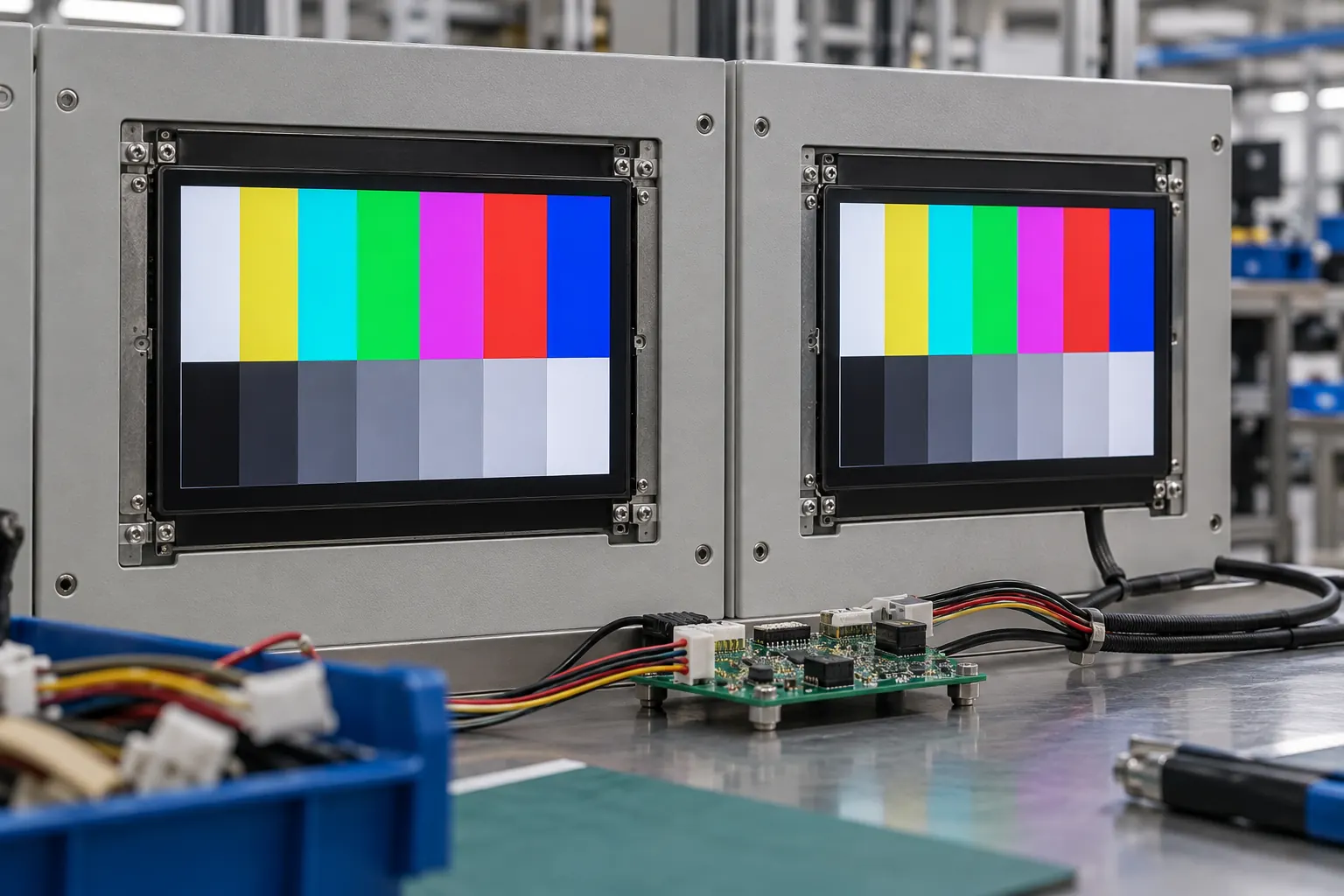 Review replacement samples beside the approved module, not in isolation.
Include the assembled interface in the final review
The panel viewed on a bench is not always the panel operators see. A cover lens, touch sensor, polarizer orientation, bezel, adhesive, or enclosure opening can alter reflections and the perceived contrast of the finished display. Recheck the approved graphics after installing the module in a representative assembly, with the intended cover and the normal room or machine lighting.
If the product includes touch, confirm that interface colors and highlights remain clear during actual operation. A capacitive-touch TFT option should be evaluated as a complete optical stack with the planned cover and bonding method. Keep module comparison separate from final usability approval: the color match may pass while a control remains hard to read at the installed angle.
Put the acceptance plan in the RFQ
When requesting samples, send the use case, expected viewing positions, final artwork or representative screens, host hardware, firmware status, brightness settings, assembly details, and inspection method. Ask the supplier to confirm which items can be measured, which will be assessed visually, and how an engineering change will be communicated. If a specific visual tolerance matters, agree on its measurement conditions before the first production order.
These steps make replacement and lot review more predictable without assuming every TFT module will look identical by default. Share your approved graphics, viewing conditions, and enclosure plan with Sunshine Display’s team when comparing modules for an industrial OEM design.