A control-cabinet HMI must connect the operator workflow, cabinet mechanics, and industrial electrical environment.
Industrial control cabinets sit at the center of automation equipment, power systems, pumps, compressors, process skids, test stations, and production lines. The HMI on the cabinet door is where operators start equipment, acknowledge alarms, select recipes, review status, and begin fault finding. An industrial control cabinet HMI display must therefore be selected around the complete machine and electrical environment, not simply around diagonal size.
For OEM teams, the best result comes from coordinating the TFT LCD module, touch technology, controller link, cabinet mechanics, front cover, electrical layout, and production lifecycle. Sunshine Display supplies industrial display modules for OEM applications, including TFT LCD modules up to 32 inches and integrated display assemblies.
Begin With the Operator Task
Before choosing a display, list the actions that occur at the cabinet. A small local panel may only show motor state, pressure, temperature, run hours, and a few alarms. A larger HMI can support recipe selection, process diagrams, live trends, maintenance pages, user access, and multi-zone equipment status.
Build sample interface screens early. Test the actual alarm colors, fine text, trend lines, disabled buttons, icons, and fault codes. Operators need important states to remain visible from their normal position, under the lighting found on the factory floor. A bright marketing demo does not prove that the final interface is readable.
The HMI should support the machine workflow without replacing safety hardware. Emergency stops, safety relays, and protective functions belong in the appropriate machine safety architecture, even when their status is presented on screen.
Match Screen Size and Viewing Angle to the Cabinet
Screen size follows viewing distance, available door space, the amount of information, and processor capability. Compact modules can work well on local service panels and distributed I/O boxes. Medium and larger displays can reduce page switching on main control cabinets where operators monitor several devices or process zones.
Review the active area, module outline, thickness, mounting holes, door opening, bezel width, connector clearance, FPC bend radius, and access for future service. The cabinet door may flex or transfer vibration, so display mounting pressure should be controlled. Uneven force can create visible mura, light leakage, or touch instability.
Operators often read the screen from standing, seated, or side positions. An IPS TFT LCD module can provide stable contrast and color across a wider viewing angle than a narrow-viewing-angle panel. Confirm the result using the real front cover and cabinet installation angle.
Treat the Front Stack as an Engineering Decision
The front surface affects readability, touch response, cleaning, and robustness. A cover lens can protect the module and give the cabinet a finished interface, but its thickness, surface treatment, printing, bonding, and gasket arrangement must work with the touch system and enclosure.
For touch-driven interfaces, a capacitive touch TFT LCD module can provide a clean sealed surface. Test it with actual gloves, moisture, dust, cleaning residue, and the planned grounding scheme. Large controls, clear pressed states, and deliberate confirmation for consequential commands reduce the chance of operating errors.
Anti-glare or anti-reflective treatment may improve readability, but the decision should be based on the lighting inside the plant. Check reflections from overhead lamps, windows, polished machinery, and operator clothing before selecting a front finish.
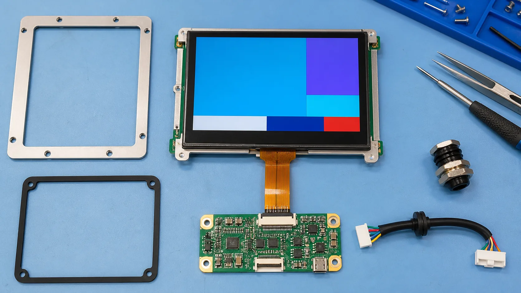 Display, touch, controller, cable, bezel, gasket, and mounting parts should be reviewed as one cabinet assembly.
Plan the Electrical and Controller Interface
The controller must support the selected resolution, timing, interface, refresh behavior, and graphics workload. RGB, LVDS, MIPI, or another link may be appropriate depending on the architecture. Communication with PLCs, drives, sensors, and remote I/O is a separate but related part of the system design.
Control cabinets can contain VFDs, contactors, relays, power supplies, heaters, and switching loads. Keep display and touch cables away from high-noise paths where possible. Review shielding, cable length, connector retention, grounding, and the return-current path before the cabinet design is released.
Power-up and recovery behavior matter as well. After an interruption, the system should return to a known state and avoid presenting old process values as current. Test boot sequences, controller resets, loss of communication, and display recovery with the final software image.
Design for Heat, Vibration, and Service Life
Cabinet temperature can rise during long operation, especially close to drives, power electronics, and enclosed process equipment. Evaluate the display, backlight, and touch system at the expected operating range. If the application sees demanding conditions, review wide-temperature TFT LCD modules together with brightness and backlight-lifetime requirements.
Vibration from pumps, motors, compressors, or transport can affect connectors and mounting. Use appropriate retention and strain relief rather than assuming the module will be protected by the cabinet alone. Consider service access: a panel that requires extensive rewiring to replace can create expensive downtime years later.
Lifecycle planning deserves early attention. Ask about module availability, controller supply, approved alternatives, PCN/EOL notification, and configuration control. These points are especially valuable for industrial equipment with a long selling and service life.
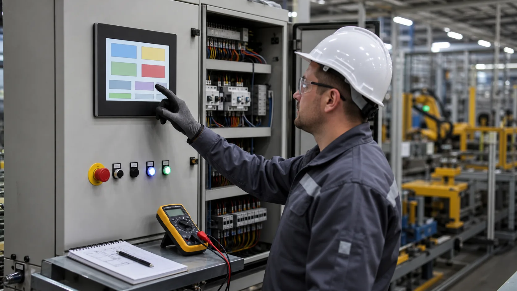 Final validation should include the actual cabinet, power equipment, grounding, cables, temperature, and operator interface.
Validate the Installed HMI
Bench testing proves basic function; the installed cabinet proves the system. Assemble representative samples and test with production wiring, normal loads, final grounding, front cover, and actual operator screens. Check display readability, touch response, noise immunity, thermal behavior, vibration, startup, fault recovery, and cleaning procedures.
Run acceptance testing with operators and service technicians. Watch how quickly they can identify alarms, switch pages, enter a recipe, and find diagnostic information. Make changes before pilot production, when UI, firmware, and mechanics can still move together.
Practical RFQ Checklist
Provide the application, desired size, active area, resolution, brightness target, viewing direction, interface, touch method, cover-lens concept, operating temperature, cabinet drawing, mounting arrangement, expected annual quantity, and lifecycle requirement. Sending representative screen layouts and cable constraints helps a display supplier make a more accurate recommendation.
Sunshine Display can review the display module and custom assembly requirements for your control cabinet project. Contact Sunshine Display to discuss a TFT LCD module, touch solution, or industrial HMI display assembly.
FAQ
What display type is suitable for an industrial control cabinet HMI?
Color TFT LCD modules are commonly used because they support graphics, alarms, trends, recipes, and touch operation. IPS technology can be useful where stable viewing angle and color are important.
Why should the HMI be tested in the final electrical cabinet?
The final cabinet introduces grounding, switching noise, cable length, vibration, temperature, front-glass reflection, and mounting pressure that may not be visible in a bench test.
Can capacitive touch work on a metal control cabinet?
Yes, but touch performance must be validated with the final cover glass, enclosure grounding, gloves, electrical noise, cleaning process, and controller firmware.