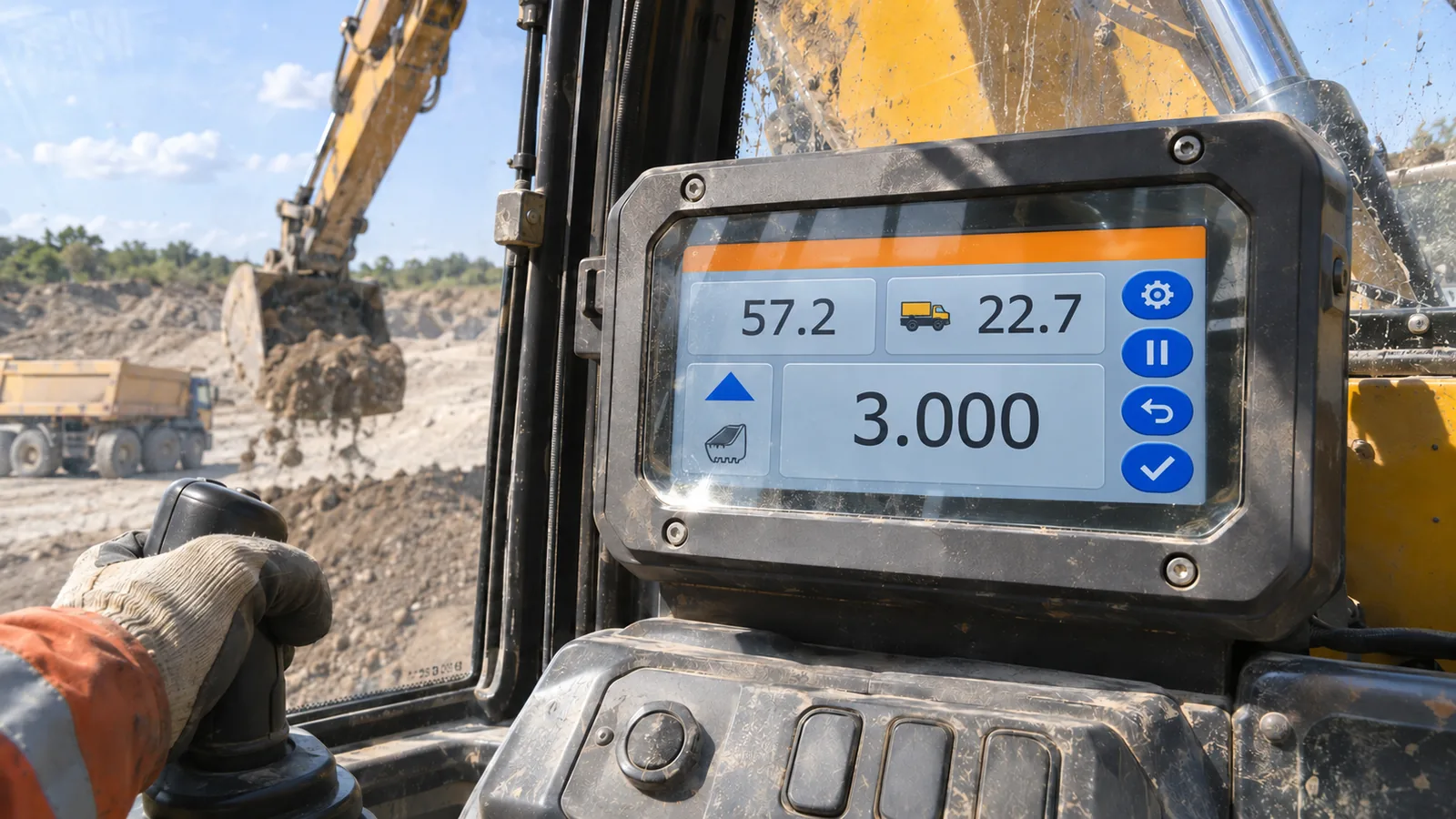
 A finished industrial HMI is judged through its protective window, not as a bare display on an evaluation board.
Quick Specs: installed-display decision snapshot
| Engineering question | What to specify or measure | Evidence type |
|---|---|---|
| Readability target | Required task, distance, angle, and illumination scene | Project input |
| Optical loss | Cover transmission, reflectance, air gap or bond | Stack measurement |
| Display contribution | White and black luminance at intended setting | Module measurement |
| Field constraint | Enclosure temperature, duty cycle, window condition | System validation |
Brightness is only one term in daylight readability
A high-brightness industrial LCD can still look washed out after it is installed behind cover glass. The reason is simple: the viewer receives both light emitted by the panel and ambient light reflected by the window and display stack. In an outdoor enclosure, the reflected component can lift the apparent black level until dark graphics, thin trends, and muted alarms lose their separation.
That is why an OEM specifying a sunlight-readable LCD behind cover glass should begin with the installed optical system. Define the task, viewing angle, window material, bezel depth, light direction, screen content, and enclosure temperature before choosing a luminance figure.
Planning bands: 300–500 cd/m² indoors, 700–1,000 cd/m² in bright industrial areas or shade, and 1,000–1,500 cd/m² or more in direct daylight. They are not acceptance criteria; front-surface reflection can defeat a high-brightness industrial LCD.
Ambient contrast ratio describes the installed problem
The useful optical measure is ambient contrast ratio (ACR), not panel brightness by itself. In a simplified diffuse-reflection model:
ACR = (L_white + R × E / π) ÷ (L_black + R × E / π)
L_white and L_black are the panel’s emitted white and black luminance in cd/m². R is installed-stack reflectance and E is display illuminance in lux. The term R × E / π estimates diffuse reflected luminance. This relationship follows ISO 9241-305; a real cover stack should still be measured because specular and diffuse reflections behave differently.
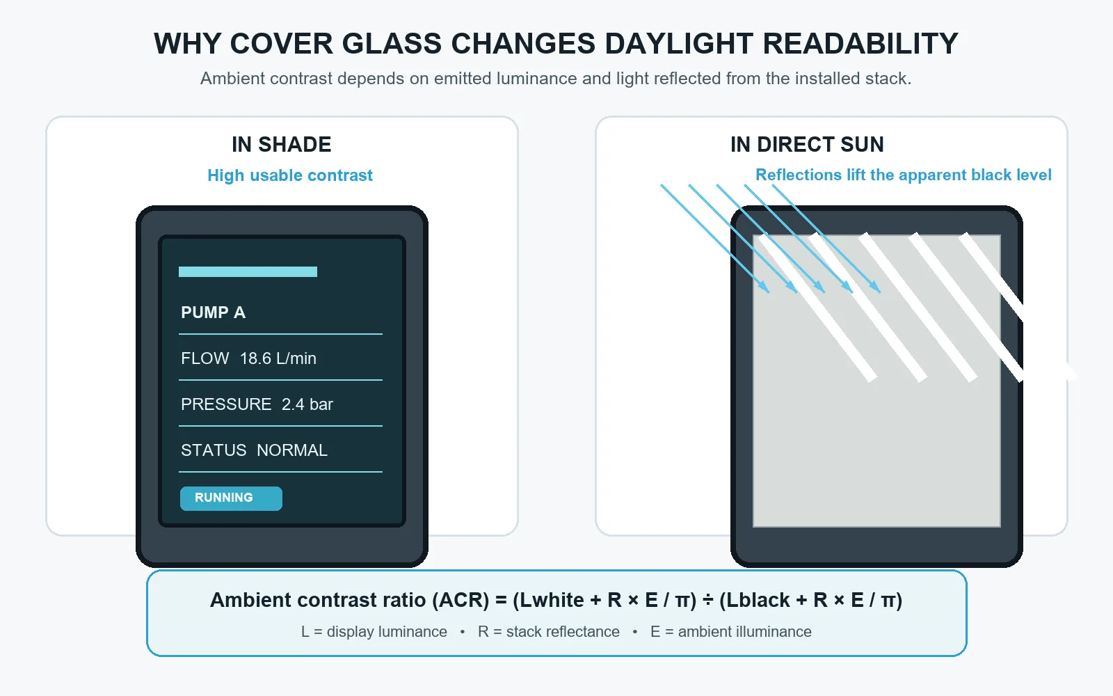 Ambient contrast falls when reflected daylight raises the apparent black level behind the cover glass; the installed stack, not the bare panel, determines the result.
Increasing panel luminance raises the numerator, but reflected light is also added to the black state in the denominator. Reducing reflection can therefore matter as much as increasing the backlight.
A modeled daylight comparison
The table below is a calculation, not a published product claim or an acceptance specification. It assumes 100,000 lux of diffuse-equivalent daylight and a native 1,000:1 panel contrast ratio. For the 1,000 cd/m² case, black is modeled as 1 cd/m²; for 2,500 cd/m², black is modeled as 2.5 cd/m². The reflected-luminance values use R × E / π and are rounded.
| Effective surface reflectance | Reflected luminance (cd/m²) | ACR at 1,000 cd/m² | ACR at 2,500 cd/m² |
|---|---|---|---|
| 12% | 3,820 | 1.3:1 | 1.7:1 |
| 4% | 1,273 | 1.8:1 | 3.0:1 |
| 0.5% | 159 | 7.2:1 | 16.4:1 |
The direction is more valuable than the exact values. A single direct-sun setup is not a uniform diffuse source, so a mirror-like reflection can be much more disruptive for one viewing direction. The practical takeaway is to evaluate the actual cover glass, air gap or optical bond, black mask, and the expected sun or luminaire geometry. Do not use this table to infer a guaranteed brightness requirement for a specific module.
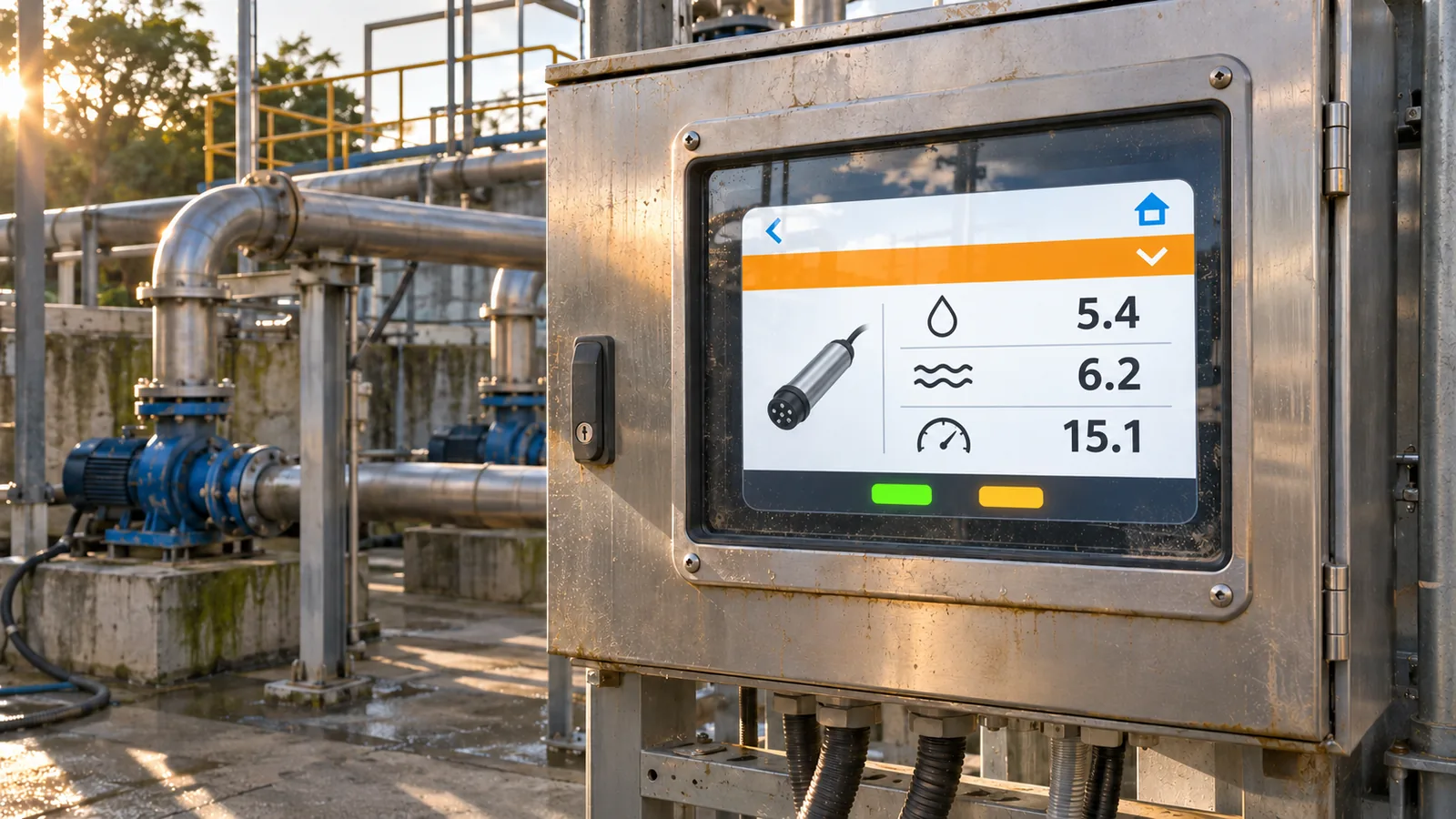 A readable installed HMI needs useful contrast after sky reflections, window contamination, and enclosure geometry are introduced.
Specify the cover stack before treating it as a mechanical detail
A cover window absorbs some of the panel’s emitted light. For example, a nominal 1,000 cd/m² panel behind a 90 percent transmitting window delivers about 900 cd/m² before surface reflections are considered. Add a glossy exterior, a printed border, an air gap, fingerprints, and the wrong light angle, and the loss in useful contrast can exceed what a small backlight increase recovers.
Ask for stack data: outer material and thickness, coating, black-print geometry, bonding method, haze, transmission, and cleaning requirements. Anti-glare treatment can soften hotspots into haze; anti-reflective treatment can reduce reflected energy. Optical bonding can reduce internal interfaces but changes rework, thermal, and service decisions.
With the cover stack defined, test the SDT035BQSI-10 TFT LCD module and SDT043GPHC-06 TFT LCD module behind the final window. Hold the glass, bonding, brightness control, HMI content, viewing angle, and illumination constant; a bare-module check cannot predict installed readability.
Let real operating content drive the test
Validate a screen that resembles the product’s work, not a colorful demonstration page. A pump control panel may need a prominent process value, an equipment schematic, and unmistakable state indicators. A construction-machine HMI may prioritize a hydraulic state, warning color, and operator action. The screen should not depend on tiny labels or pale trends that disappear at the expected distance.
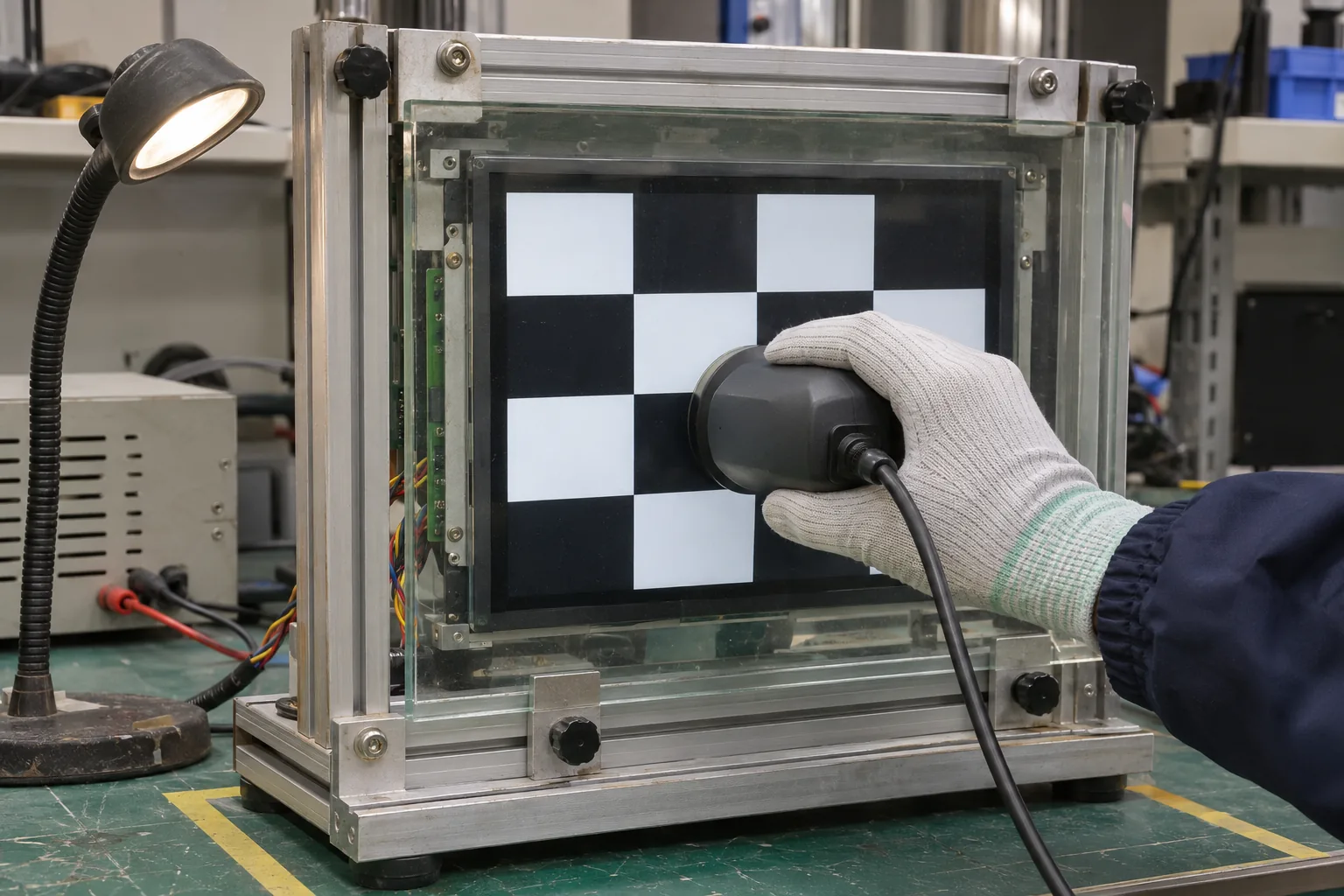 An ANSI checkerboard measurement makes the white and black states visible under a representative glass stack, rather than judging a bare module in ideal light.
For an optical validation unit, inspect a solid gray field, a black field, full white, and an ANSI-style checkerboard. Record viewing angle, illumination direction, glass condition, and panel setting with each observation. If touch is required, test the finished stack with the intended cover thickness, moisture condition, grounding design, and gloves; capacitive touch TFT LCD modules should be assessed as an assembly, not as a loose module.
Brightness also changes thermal and power margins
Higher backlight output can be necessary, but it adds heat and power draw. In a sealed enclosure, solar loading, processor heat, backlight energy, adhesives, and power conversion share the same thermal budget. A brightness target should therefore identify its duty cycle and maximum installed temperature.
Where operating temperature is a selection constraint, include the SDT050BWSI-04 wide-temperature TFT LCD module in the installed thermal and optical validation. Select from module data, the cover stack, and enclosure heat path.
Send a measurable RFQ
An effective RFQ for an outdoor readable TFT display includes active-area limits, orientation, host interface, target display content, viewing distance and angle, cover glass material and thickness, coating or bonding preference, illumination scenarios, operating temperature, brightness control behavior, annual volume, and lifecycle requirements. Define the acceptance scene: which content must remain readable at which angle and light condition.
That brief lets the supplier recommend an optical system instead of quoting a brightness number. Contact Sunshine Display with the enclosure concept, cover-stack details, and representative HMI screens.
References & Sources
- NIST: Display Daylight Ambient Contrast Measurement Methods and Daylight Readability — contrast method.
- ISO 9241-305 — visual ergonomic test methods and ambient-contrast formulation; use the applicable edition.
- FAA HF-STD-001B, glare-control guidance — reflections, glare, and legibility near sunlight.
- Sunshine Display product pages — module-family context only; part selection requires a data sheet.