A long, narrow TFT display can make a control panel easier to scan when it is used for a status strip, process lane, queue, or compact instrument readout. It can also create avoidable mechanical mistakes because the visible image is only one dimension of a long assembly. The active area, overall outline, mounting references, bezel opening, connector position, and flex-cable bend space must agree before a housing is released.
Evaluate the long display in the same panel geometry planned for the equipment.
Begin with the visible area, not the diagonal
For a bar-type TFT LCD design, first define what the operator must see. Measure the space available for the visible information, then distinguish it from the opening in the cover and from the module outline behind it. A bezel opening that simply matches a nominal display size can hide pixels at one end, reveal unwanted edges, or leave too little tolerance for assembly variation. Bring the actual screen layout to the review: a long alarm label, a row of channel states, or a trend strip can expose a poor cutout decision earlier than a generic demo image.
A standard TFT LCD module can be a starting point for comparing industrial formats, but the sample must be checked against the intended front panel. Note the active area, the inactive border, the module outline, and the mounting surface separately on the enclosure drawing. Do not assume that an image centered on a desktop sample will remain centered after the display is registered to a long molded or machined opening.
Confirm orientation with the real cable route
Bar modules are often mounted horizontally, vertically, or at a slight panel angle. Rotation changes more than the way graphics are composed. It changes where the FPC exits, the direction of a connector, the available bend radius, and the relationship between the cable and nearby fasteners or ribs. Choose the orientation after the complete panel stack is visible, not just after the UI has been laid out.
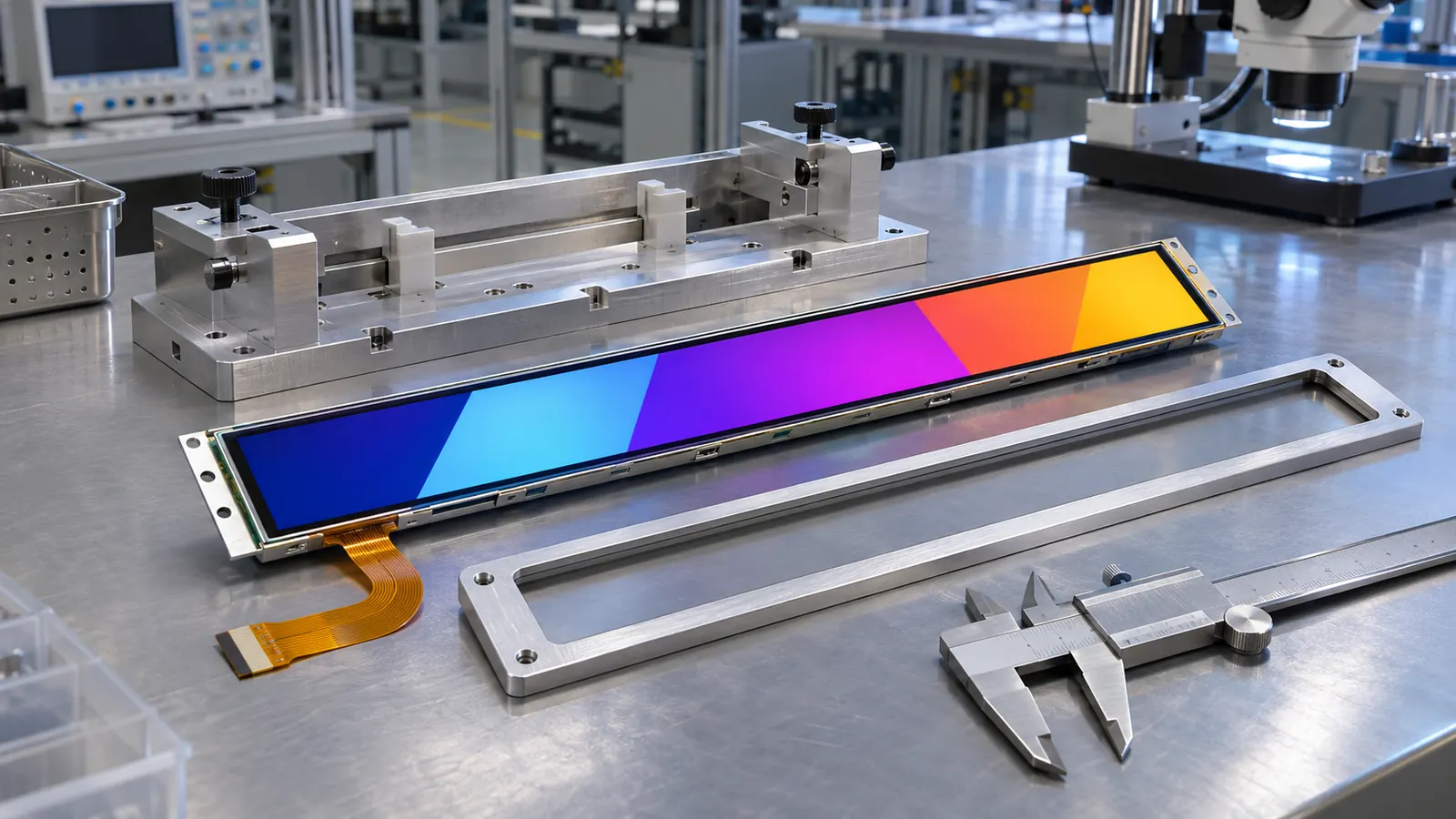 Check active area, cutout edges, mounting references, and cable direction together.
Make a simple mechanical sample with the actual cable or a representative substitute. Confirm that the FPC can reach the host board without twisting at the connector, being pinched by the bezel, or crossing a service zone. If a connector needs to be disconnected in the field, check whether a technician can reach it with the unit mounted. These practical checks are usually more useful than adding nominal clearance to a drawing without seeing the assembly.
Let the information shape the panel
Long displays work best when content follows the available width. Keep critical states legible from the required distance and avoid making a narrow strip carry several unrelated dense screens. When operators approach from one side of a machine, test the same text size and color states at that approach angle. If wider viewing behavior is important, compare the candidate format with an IPS TFT LCD option using the final graphics.
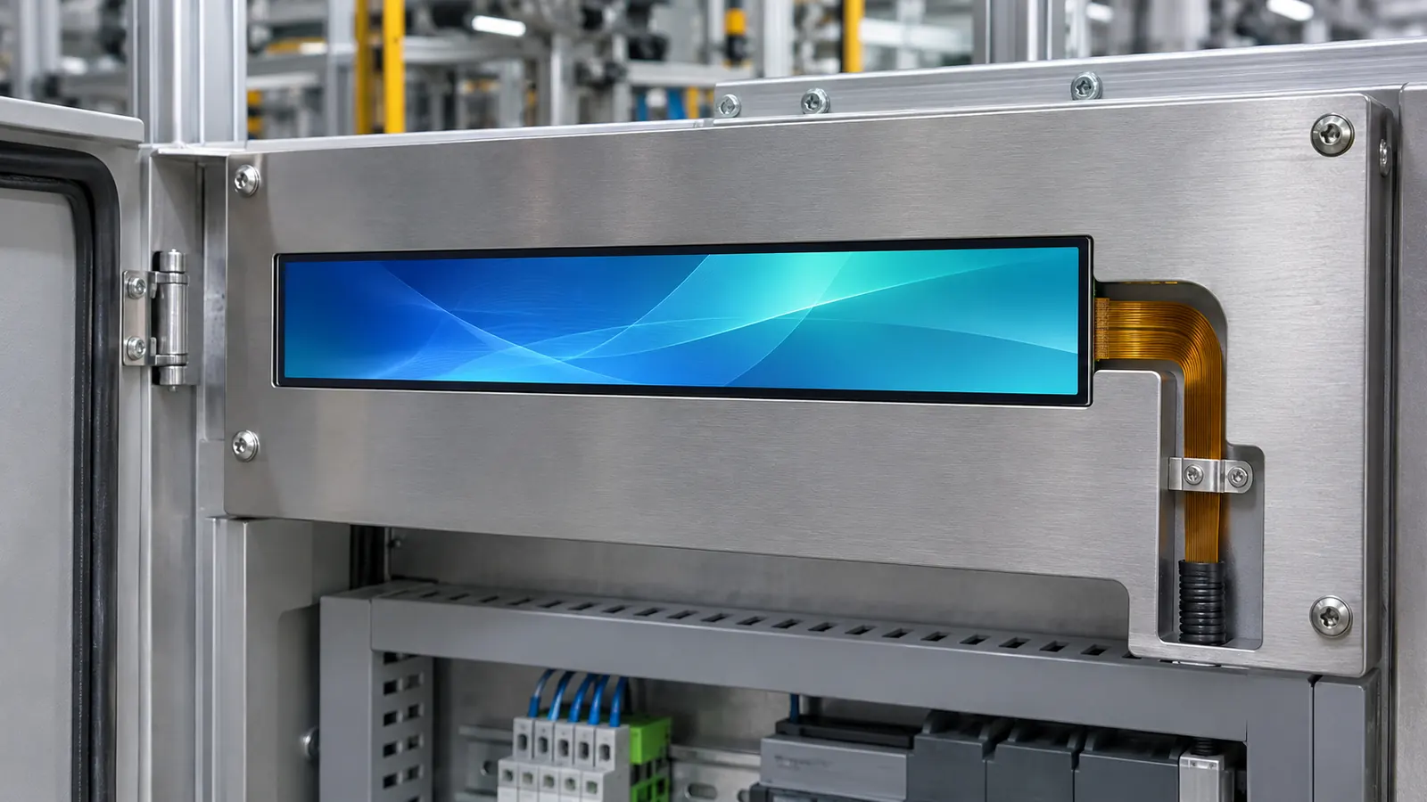 Protect FPC clearance and service access after the display is installed.
The final decision is a stack decision: display, cover, cutout, mounting, cable, controller, and content. A bar display that fits mechanically but cannot be serviced, or that looks correct only from one point, has not yet solved the integration problem.
Set the datum strategy early
Long modules make it especially important to agree which physical features locate the display. A housing may reference a mounting hole, an outer edge, a front bezel, or a rear support. If different teams use different references, a display can be electrically connected yet visually offset. Put the datum approach on the mechanical review drawing and check it with tolerances that reflect the production assembly rather than a hand-aligned prototype.
Think about the front lens or printed mask as part of that datum strategy. A dark mask can improve the front appearance, but it can also reduce the usable opening when its position drifts. Confirm the minimum visible active area across expected variation. The same review should ask whether the module is supported evenly; a long part should not depend on a cable or a narrow edge for its mechanical position.
Review replacement as a sequence
Write the replacement steps while the sample is open: remove the front part, release the cable, remove the support, fit the replacement, reconnect it, and verify the image. If any step risks bending the FPC sharply, scratching the lens, or losing an alignment reference, improve the assembly before production. A serviceable bar display is easier to keep in use throughout the equipment lifecycle.
Validate the finished assembly
Bench approval should not be the final decision. Build a sample with the intended module, controller, cable, mounting method, front lens or bezel, and representative firmware. Check the screen from the positions available to operators, then repeat the checks after a restart, a power interruption, and a service-access exercise. Record what was tested rather than relying on a general impression that the display looked acceptable.
Document the part number, active area, outline, interface, display orientation, host software revision, backlight or drive setting, mounting details, and screen examples used during the review. When a display, enclosure, controller, or cable changes later, that record gives engineering and purchasing teams a meaningful baseline for deciding whether another sample review is needed.
Make the RFQ support the product lifecycle
An OEM request should describe the operator task and equipment environment alongside size and resolution. Include available space, viewing position, interface, expected operating conditions, service access, annual demand, lifecycle expectations, and the validation build. A clear brief helps identify mechanical and electrical questions before a housing or firmware is locked. Sunshine Display can help teams compare industrial display modules against an enclosure and integration plan through the contact page.
Before releasing the design, define the acceptance sample and the evidence that accompanies it. That can include the module identification, installation drawing, image or screen set, test conditions, observations, and the responsible reviewer. Keep the approved reference assembly available where practical. It is often the fastest way to understand whether a later change in material, controller, cable, display orientation, or enclosure has altered the result that the team originally accepted.
Avoid treating a display as a cosmetic item after the first prototype works. The screen is an operator interface, an electrical load, a mechanical component, and a service item at the same time. A short cross-functional review between mechanical, electrical, firmware, quality, and purchasing teams can expose a gap before it becomes a field issue.