Review the module, window and enclosure as one mechanical assembly.
A TFT module fits the opening in a prototype enclosure, yet the finished assembly is difficult to build. The cable needs more room than the drawing allowed, a connector latch disappears behind a bracket, and tightening the front panel changes how the display sits. None of these problems is answered by the screen's diagonal size.
TFT display mounting for industrial enclosures should be reviewed as an assembly, not as a rectangular cutout. The module, protective window, touch sensor, support frame, cable, and host board occupy different spaces and carry different loads. A useful mechanical review starts with those relationships before tooling or production fixtures are released.
Work from the module drawing, not the visible image
Distinguish the active display area, viewing opening, external outline, and mounting features. The active area describes where an image appears; it does not tell the enclosure designer where the part can be supported. Likewise, a bezel that frames the picture neatly may conceal a critical attachment point or cable exit.
Obtain the controlled mechanical drawing for the exact module revision. Confirm the dimensions, tolerances, connector position, flexible cable geometry, and any restricted contact areas with the supplier. If a drawing leaves the mounting method unclear, resolve that question before assuming that the metal frame or glass edge can accept the intended load.
When comparing standard TFT LCD modules, put candidate outlines into the same enclosure model. Include the rear components and cable path. Two modules with the same nominal diagonal may require different supports and different assembly sequences.
Decide what supports the display
Identify the intended load path from the display assembly to the enclosure. Document which brackets, pads, attachment features, or other approved supports locate the module. Avoid relying on a cable, connector, or loosely trapped front window to hold the assembly in position.
Ask the module supplier about permitted mounting arrangements and any relevant restrictions. Do not invent a screw torque, clamping force, adhesive specification, or clearance from a sample photograph. Those details belong in the agreed mechanical design and assembly instructions for the actual components.
Consider how the enclosure behaves when its own fasteners are tightened. A display that sits correctly in an open frame may be loaded differently after the rear cover and front fascia are installed. Evaluate the completed assembly and inspect the image as well as the physical fit. Record any change during fastening so the team can investigate it rather than treating it as normal variation.
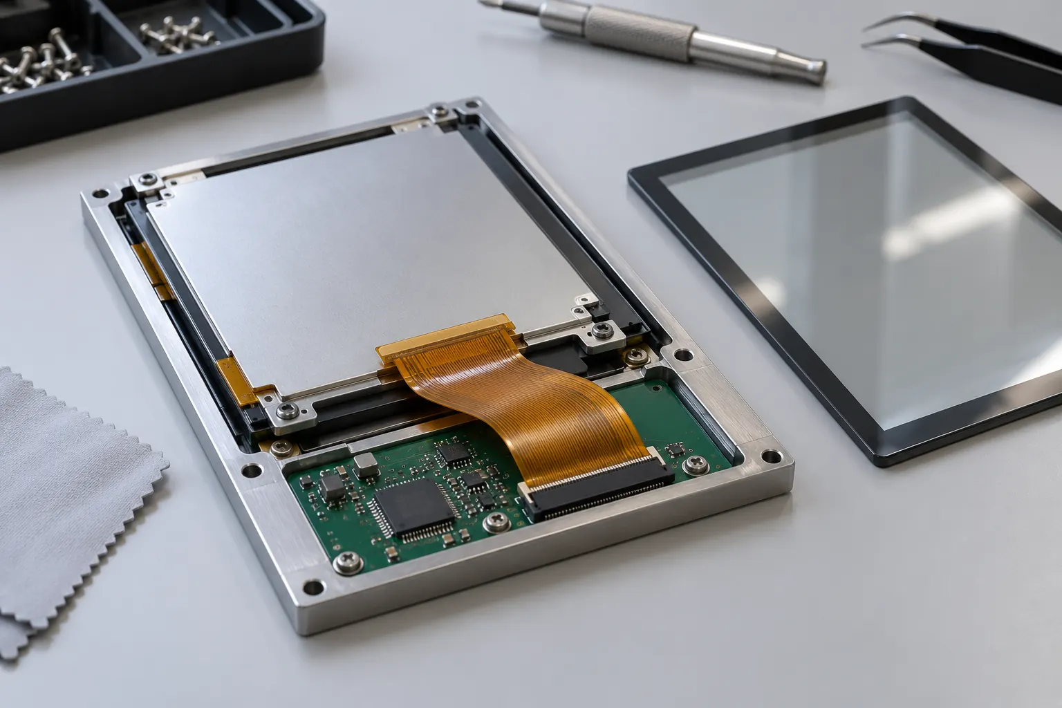 Reserve space for the cable route and connector operation.
Reserve room for the cable and the person connecting it
Model the cable in its installed route, including the connector's insertion direction and latch movement. Follow the supplier's guidance for bending and handling. A route that works while the module is loose may become impractical once the supports are fixed and the controller board is installed.
Check for sharp edges, trapped sections, contact with fastener tips, and movement as a door or cover closes. Do not pull a flexible cable taut simply to make the model look tidy. Give the electrical and mechanical teams a shared view of the route so grounding, signal integrity, and service access can be reviewed together.
Then ask an assembler to follow the proposed sequence with representative parts. Can the connector be seen? Can its latch be operated without levering against the display? Is there a clear way to confirm full insertion? These questions often reveal a bracket or board position that needs to change before production.
Treat the front window as another engineered component
Review the window opening, surface treatment, alignment, and relationship to the display. Inspect the result under the lighting expected at the machine. A clean rendering does not show every reflection or obstruction that an operator may encounter from an angled position.
If touch is required, agree on the complete stack before choosing the enclosure details. Cover construction, sensor placement, controller configuration, and installation can affect the result. Discuss TFT modules with capacitive touch using the proposed cover and mounting arrangement, then validate the selected assembly with representative operating conditions.
Keep enclosure protection claims tied to the finished product and its test evidence. A front gasket or protective lens does not by itself establish a dust or water rating. Define how the seal is compressed, how the enclosure is assembled, and which tests the responsible team requires.
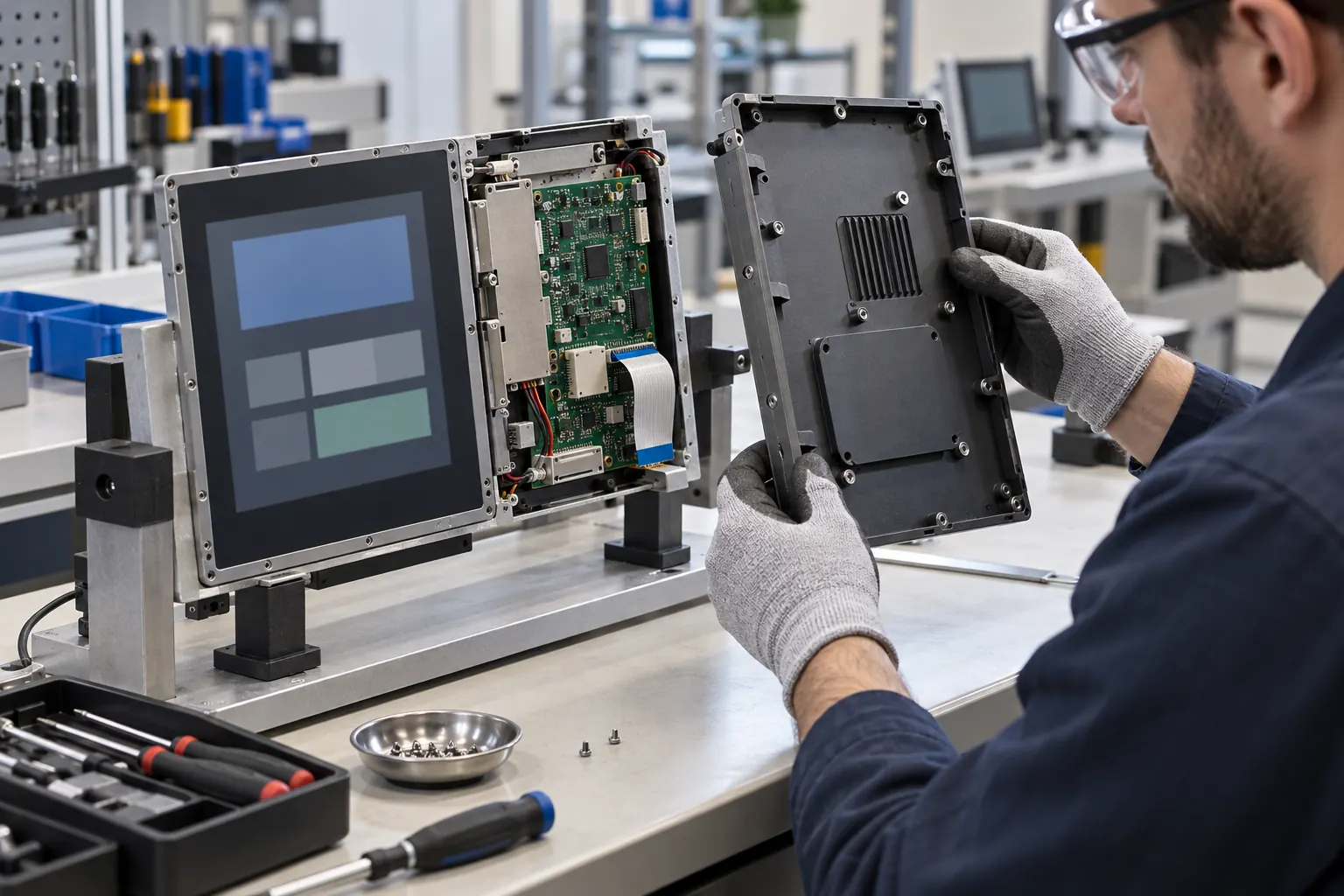 Check the removal sequence as well as the initial assembly.
Check variation before it becomes a production surprise
Review the tolerance chain between the enclosure opening, mounting features, display position, and front window. Include the tolerances of purchased parts and the processes used to locate them. A nominally centered sample does not show how much image area could be obscured at the limits of the design.
Use representative parts to evaluate alignment and assembly effort. Define observable acceptance criteria: the intended image area is visible, the cable is not pinched, connectors are seated, supports are in contact where required, and the enclosure closes without forcing parts into place. Keep inspection practical enough for the planned production process.
Where the equipment will experience vibration, temperature changes, or repeated handling, have the engineering team define appropriate assembly-level evaluation. Do not assume that a module specification covers every bracket, adhesive, connector, and enclosure joint around it. Record the tested construction so later substitutions can be reviewed against the same baseline.
Plan the second assembly as carefully as the first
Service work exposes different weaknesses from initial production. Decide how a technician removes the display, disconnects the cable, and protects the window and sensor during replacement. Check whether the removal sequence requires disturbing unrelated wiring or destroying a component that was intended to be reusable.
Identify items that must be renewed after opening, and include them in the service plan. Photograph or document connector orientation and cable routing so that a replacement does not depend on remembering how the original unit looked. Keep the replacement module revision and any required electrical checks linked to the service instructions.
Before committing to an enclosure design, send the module candidate, section drawing, cable route, and assembly sequence to Sunshine Display's OEM enquiry team. Those details make it easier to discuss the mounting approach and identify questions that a sample build should settle before production.